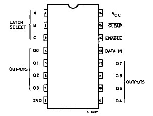
Features: `HIGH SPEED tPD = 15 ns (TYP.) AT VCC = 5 V `LOWPOWER DISSIPATION ICC = 4 A (MAX.) AT TA = 25 ° C `OUTPUT DRIVE CAPABILITY10 LSTTL LOADS `SYMMETRICAL OUTPUT IMPEDANCE IOL = |IOH |= 4 mA (MIN.)`HIGH NOISE IMMUNITY VNIH = VNIL = 28 % VCC (MIN.) `WIDE OPERATING VOLTAGE RANGE VCC (OPR) = 2 V...
M54HC259: Features: `HIGH SPEED tPD = 15 ns (TYP.) AT VCC = 5 V `LOWPOWER DISSIPATION ICC = 4 A (MAX.) AT TA = 25 ° C `OUTPUT DRIVE CAPABILITY10 LSTTL LOADS `SYMMETRICAL OUTPUT IMPEDANCE IOL = |IOH |= 4 mA (M...
SeekIC Buyer Protection PLUS - newly updated for 2013!
268 Transactions
All payment methods are secure and covered by SeekIC Buyer Protection PLUS.
Symbol |
Parameter |
Value |
Unit |
VCC |
Supply Voltage |
-0.5 to +7 |
V |
VI |
DC Input Voltage |
-0.5 to VCC + 0.5 |
V |
VO |
DC Output Voltage |
-0.5 to VCC + 0.5 |
V |
IIK |
DC Input Diode Current |
± 20 |
mA |
IOK |
DC Output Diode Current |
± 20 |
mA |
IO |
DC Output Source Sink Current Per Output Pin |
± 35 |
mA |
ICC or IGND |
DC VCC or Ground Current |
± 70 |
mA |
PD |
Power Dissipation |
500 (*) |
mW |
Tstg |
Storage Temperature |
-65 to +150 |
°C |
TL |
Lead Temperature (10 sec) |
300 |
°C |
The M54/74HC259 is a high speed CMOS 8 BIT ADDRESSABLE LATCH fabricated in silicon gate C2MOStechnology. It has the same highspeed performance of LSTTL combined with true CMOS low power consumption.
The M54HC259/M74HC259 has single data input (D) 8 latch outputs (Q0-Q7), 3 address inputs (A, B, and C), common enable input (E), and a common CLEARinput. To operate this device as an addressable latch, data is held on the D input, and the address of the latch into which the data is to be entered is held on the A, B, and C inputs. When ENABLE is taken low the data flows through to the addresses output. The data is stored on the positive-going edge of the ENABLE pulse. All unaddressed latches will remain unaffected. With ENABLE in the high state the device is deselected and all latches remain in their previous state, unaffected by changes on the data or address inputs. To eliminate the possibility of entering erroneous data into the latches, the ENABLE should be held high (inactive) while the addresslines are changing. IfENABLE is held highand CLEAR is taken low all eight latches are cleared to the lowstate. IfENABLE is lowall latches except the addressed latch will be cleared. The addressed latch will instead follow the Dinput, effectively implementing a 3-to 8 line decoder.
All inputs are equipped with protection circuits against static discharge and transient excess voltage.