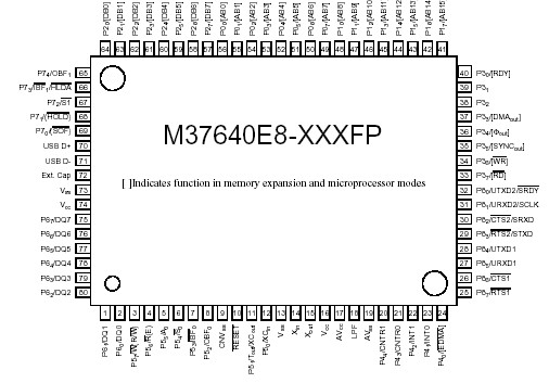
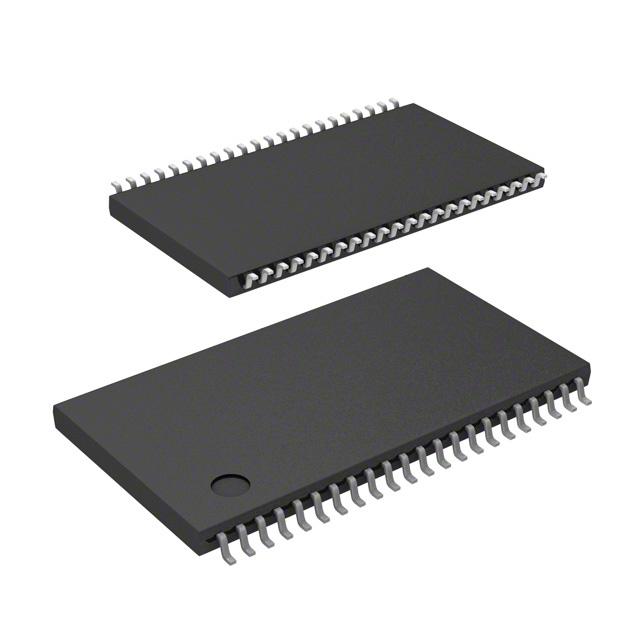
Features: • 7600 8-bit CPU core, CMOS process
• Minimum instruction execution time of 83ns (1-cycle instruction @ F = 12 MHz)
• Efficient software support (C and/or Assembly)
• ROM: 32 KB on-chip
• RAM: 1 KB on-chip
• Built-in Microprocessor or Memory-expansion modes
• Three slow memory wait modes: Software Wait, RDY Wait, and Extended RDY Wait
• Nine I/O Ports, total 66 programmable I/O pins available
• Programmable direction control on every I/O pin
• Software selectable slew rate control on every I/O pin
• Master CPU Bus Interface:
• MCU can be operated in slave mode by control signals from the host CPU
• 8 data lines (DQ7-DQ0) and R(E), W(R/W), A0, S0, S1, IBF0, OBF0, IBF1, OBF1 signals available
• Master CPU sends and receives data, command, and status by means of DQ7-DQ0
• USB Function Control Unit
• USB Transceiver (conforms to USB V1.1 Specification)
• DMA Controller:
• Two DMA channels available
• 16 address lines for 64K byte address space
• Single byte or burst transfer modes
• Transfer request by external pins, software triggers or built-in peripherals
• Maximum 6M byte/sec transfer speed (in burst mode)
• Timers: three 8-bit timers and two 16-bit timers available
• Two full duplex UARTs available
• One master/slave clock synchronous I/O (SIO), internal or external clock selectable
• Built-in Special Count Source Generator (SCSG): can be a clock source for Timer X, UARTs, and SIO
• Power-saving wait (IDLE) and stop (powerdown) modes.Pinout Specifications
|
Symbol |
Parameter |
Conditions |
Limits |
Unit |
|
VCC
|
Power supply
|
|
-0.3 to 7.0
|
V |
|
AVCC |
Analog power supply |
|
-0.3 to VCC + 0.3 |
V |
|
VI |
Input voltage P0, P1, P2, P3, P4, P5, P6, P7, P8
|
Values are with respect to
VSS. Output transistors are
in off state. |
-0.3 to VCC + 0.3 |
V |
|
VI |
Input voltage RESET, Xin, XCin |
-0.3 to VCC + 0.3 |
V |
|
VI |
Input voltage CNVSS
|
-0.3 to 13 |
V |
|
VI |
Input voltage USB D+, D- |
-0.5 to 3.8V
|
V |
|
VO |
Output voltage P0, P1, P2, P3, P4, P5, P6, P7, P8, Xout,
XCout, LPF
|
|
-0.3 to VCC + 0.3 |
|
|
PD |
Power dissipationNote 1 |
Ta = 25°C |
750
|
mW |
|
TOPR |
Operating temperature
|
|
-20 to +85 |
°C |
|
TSTG |
Storage temperature |
|
-40 to +125 |
°C
|
DescriptionAn on-chip oscillator M37640E8-XXXF provides the system and peripheral clocks as well as the USB clock necessary for operation. This oscillator circuit is comprised of amplifiers that provide the gain necessary for oscillation, oscillation control logic, a frequency synthesizer, and buffering of the clock signals. A flow diagram for the oscillator circuit is shown in Figure 2-6 and a block diagram of the oscillator circuit of M37640E8-XXXF is shown in Figure 2-7. The following external clock inputs are supported:
• A quartz crystal oscillator of up to 24 MHz, connected to the Xin and Xout pins.
• An external clock signal of up to 48 MHz, connected to the Xin pin.
• A ceramic resonator or quartz crystal oscillator of 32.768 kHz, connected to the XCin and XCout pins.
• An external clock signal of up to 5.12 MHz, connected to the XCin pin.
The frequency synthesizer M37640E8-XXXF can be used to generate a 48MHz clock signal (fUSB) needed by the USB block and clock fSYN, which can be chosen as the source for the system and peripheral clocks. Both fUSB and fSYN are phase-locked frequency multiples of the frequency synthesizer input. The inputs of M37640E8-XXXF to the frequency synthesizer can be either Xin or XCin.
The two-phase non-overlapping system clock M37640E8-XXXF (CPU and peripherals) is derived from the source to the clock circuit and is 1/2 the frequency of the source. (i.e. Source = 24 MHz, system clock = 12 MHz) Any one of four clock signals can be chosen as the source for the system and peripheral clocks; fXin/ 2, fXin, fXCin, or fSYN. The selection of M37640E8-XXXF is based on the values of bits CPMA6, CPMA7 and CCR7. The default source after reset is fXin/2.
The default source of M37640E8-XXXF for the system and peripheral clocks is fXin/2. If fXin = 24MHz, then the CPU will be running at F = 6MHz (low frequency mode. For the CPU to run in high frequency mode, i.e., source of clock = fXin, write a "1" to bit 7 of the clock control register.
The drive strength of the Xout and XCout inverting amplifier M37640E8-XXXF can be controlled by bits CPMB7 and CPMA3, respectively. High drive is the default at reset or after executing a STP instruction and must be chosen whenever restarting Xin or XCin oscillation if a ceramic or crystal oscillator is used. When oscillation M37640E8-XXXF has been established, low drive can be selected to reduce power consumption. If an external clock signal is input to Xin or XCin, the inverting amplifiers M37640E8-XXXF can be disabled by means of the CCR6 and CCR7 bits, respectively, in order to reduce power consumption.

 M37640E8-XXXF Data Sheet


