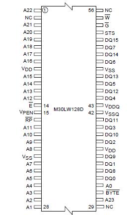
Features: TWO M58LW064D 64Mbit FLASH MEMORIES STACKED IN A SINGLE PACKAGE WIDE x8 or x16 DATA BUS for HIGH BANDWIDTH SUPPLY VOLTAGE VDD = 2.7 to 3.6V for Program, Erase and Read operations VDDQ = 1.8 to VDD for I/O buffers ACCESS TIME Random Read 110ns Page Mode Read 110/25ns PROGRAMMING TIME...
M30LW128D: Features: TWO M58LW064D 64Mbit FLASH MEMORIES STACKED IN A SINGLE PACKAGE WIDE x8 or x16 DATA BUS for HIGH BANDWIDTH SUPPLY VOLTAGE VDD = 2.7 to 3.6V for Program, Erase and Read operations VDDQ =...
SeekIC Buyer Protection PLUS - newly updated for 2013!
268 Transactions
All payment methods are secure and covered by SeekIC Buyer Protection PLUS.
US $.6 - .9 / Piece
Schottky (Diodes & Rectifiers) 40 Volt 30 Amp Dual Common-Cathode
US $.38 - .53 / Piece
Schottky (Diodes & Rectifiers) 45 Volt 30 Amp Dual Common-Cathode
Symbol |
Parameter |
Value |
Unit | |
Min |
Max | |||
TBIAS |
Temperature Under Bias |
40 |
125 |
°C |
TSTG |
Storage Temperature |
55 |
150 |
°C |
VIO |
Input or Output Voltage |
0.6 |
VDDQ +0.6 |
V |
VDD,VDDF |
Supply Voltage |
0.6 |
5.0 |
V |
IOSC |
Output Short Circuit Current |
|
100(1) |
mA |
The M30LW128D is a 128 Mbit device that is composed of two separate 64 Mbit M58LW064D Flash memories. The device can be erased electrically at block level and programmed in-system using a 2.7V to 3.6V (VDD) supply for the circuitry and a 1.8V to VDD (VDDQ) supply for the Input/Output pins.
The bus width M30LW128D can be configured for x8 or x16 for the devices available in the TSOP56 (14 x 20 mm) and TBGA64 (10x13mm, 1mm pitch) packages. The bus width is set to x16 for the devices available in the LFBGA88 (8x10mm, 0.8mm pitch) package.
Each internal M58LW064D has 3 Chip Enable signals to allow up to 4 memories to be connected together without the use of additional glue logic. In this way the address space is contiguous and the microprocessor only requires one Chip Enable, E, to control both memories.
The M30LW128D is divided into 128 blocks of 1Mbit (2 x 64 x 1Mb) that can be erased independently so it is possible to preserve valid data while old data is erased. Program and Erase commands are written to the Command Interface of the device. An onchip Program/Erase Controller (P/E.C) simplifies the process of programming or erasing the device by taking care of all of the special operations that are required to update the memory contents. The end of a Program or Erase operation can be detected and any error conditions identified in the Status Register. The command set required to control the device is consistent with JEDEC standards.
The Write Buffer M30LW128D allows the microprocessor to program from 1 to 16 Words in parallel, both speeding up the programming and freeing up the microprocessor to perform other work. A Word Program command is available to program a single word.
Erase M30LW128D can be suspended in order to perform either Read or Program in any other block and then resumed. Program can be suspended to Read data in any other block and then resumed. Each block can be programmed and erased over 100,000 cycles.
Individual block protection against Program or Erase M30LW128D is provided for data security. All blocks are protected during power-up. The protection of the blocks is non-volatile; after power-up the protection status of each block is restored to the state when power was last removed. Software commands are provided to allow protection of some or all of the blocks and to cancel all block protection bits simultaneously. All Program or Erase operations are blocked when the Program Erase Enable input VPEN is low.
The Reset/Power-Down pin M30LW128D is used to apply a Hardware Reset to the enabled memory and to set the device in power-down mode.
The STS signal M30LW128D is an open drain output that can be used to identify the Program/Erase Controller status. It can be configured in two modes: Ready/ Busy mode where a static signal indicates the status of the P/E.C, and Status mode where a pulsing signal indicates the end of a Program or BlockErase operation. In both modes it can be used as a system interrupt signal, useful for saving CPU time. The STS signal is only available with the TSOP56 and TBGA64 packages.
Each memory M30LW128D includes a 128 bit Protection Register. The Protection Register is divided into two 64 bit segments, the first one is written by the manufacturer (contact STMicroelectronics to define the code to be written here), while the second one is programmable by the user. The user programmable segment can be locked.