Features: ` Pin Confi gurable Gain and Filter Response Up to 28MHz
`Few External Components Required
`Resistors Trimmed to 0.5% Typical
`Capacitors Trimmed to 0.5% Typical
`Very Low Noise: 80dB S/N in 100MHz Bandwidth
`Very Low Distortion (2VP-P):
1MHz: 100dBc 2nd, 123dBc 3rd
10MHz: 72dBc 2nd, 103dBc 3rd
`Adjustable Output Common Mode Voltage
`Rail-to-Rail Output Swing
`Power Confi gurability and Low Power Shutdown
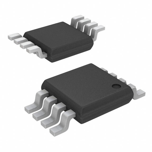
`Tiny 0.75mm 20-Lead (4mm * 4mm) QFN PackageApplication· Differential Input A/D Converter Driver
· Antialiasing/Reconstruction Filter
· Single-Ended to Differential Conversion/Amplifi cation
· Low Voltage, Low Noise, Differential Signal Processing
· Common Mode Voltage TranslationPinout Specifications
Total Supply Voltage (V+ to V) ................................5.5V
Input Voltage (Any Pin) (Note 2) ..V+ + 0.3V to V 0.3V
Input Current (VOCM, BIAS) ..................................±10mA
Input Current (Pins 1, 5) (Note 2) ........................±20mA
Input Current (Pins 2, 4) (Note 2) ........................±30mA
Input Current (Pins 6, 20) (Note 2) ......................±15mA
Input Current (Pins 7, 8, 9, 10, 16, 17, 18, 19)
(Note 2) ..............................................................±10mA
Output Short-Circuit Duration (Note 3) .......... Indefi nite
Operating Temperature Range (Note 4)....40 to 85
Specifi ed Temperature Range (Note 5) ....40 to 85
Junction Temperature ........................................... 150
Storage Temperature Range ..................65 to 150
Note 1: Stresses beyond those listed under the Absolute Maximum Ratings may cause permanent damage to the device. Exposure to any Absolute Maximum Rating condition for extended periods may affect device reliability and lifetime.
Note 2: All pins are protected by steering diodes to either supply. If any pin is driven beyond the part's supply voltage, the excess input current (current in excess of what it takes to drive that pin to the supply rail) should be limited to less than 10mA.
Note 3: A heat sink may be required to keep the junction temperature below the Absolute Maximum Rating when the output is shorted indefi nitely. Long-term application of output currents in excess of the Absolute Maximum Ratings may impair the life of the device.
Note 4: The LTC6601C/LTC6601I are guaranteed functional over the operating temperature range 40 to 85.
Note 5: The LTC6601C is guaranteed to meet specifi ed performance from 0 to 70. The LTC6601C is designed, characterized, and expected to meet specifi ed performance from 40 to 85 but is not tested or QA sampled at these temperatures. The LTC6601I is guaranteed to meet specified performance from 40 to 85.
DescriptionThe LTC®6601-1 is a very easy-to-use fully differential 2nd order active RC fi lter and driver. On-chip resistors, capacitors, and amplifi er bandwidth are trimmed to provide consistent and repeatable fi lter characteristics.
The fi lter characteristics of LTC6601-1 are pin-strap confi gurable. Cutoff frequencies range from 5MHz to 28MHz. Gain is pin-strap programmable between 17dB and +17dB.
A three-state BIAS pin is provided to adjust amplifi er power consumption. Select between high performance, low power (50% power reduction), and standby modes with the BIAS pin.
The LTC6601-1 is available in a compact 4mm * 4mm 16-pin leadless QFN package.

 LTC6601-1 Data Sheet