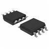
Features: SMBus and I2C CompatibleBuilt-In Charge Pumps Drive N-Channel Switches16 Available Switches on the Same Bus0.6V VIL and 1.4V VIH for DATA and CLKAvailable in 8-Lead MSOP and S0 PackagesLow Standby Current: 14mAEight Addresses from Two Three-State Address PinsInternal Power-On Reset Timer...
LTC1623: Features: SMBus and I2C CompatibleBuilt-In Charge Pumps Drive N-Channel Switches16 Available Switches on the Same Bus0.6V VIL and 1.4V VIH for DATA and CLKAvailable in 8-Lead MSOP and S0 PackagesLow...
SeekIC Buyer Protection PLUS - newly updated for 2013!
268 Transactions
All payment methods are secure and covered by SeekIC Buyer Protection PLUS.
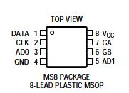
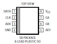
PIN FUNCTIONS
DATA: (Pin 1) Open-Drain Connected Serial Data Interface.Must be pulled high to VCC with external resistor. The pull-up current must be limited to 350mA.
CLK: (Pin 2) Serial Clock Interface. Must be pulled high to VCC with external resistor. The pull-up current must be limited to 350mA.
AD0: (Pin 3) Lower Three-State Programmable Address Pin. Must be connected directly to VCC, GND, or VCC/2 (using two resistors £ 1M). Do not float this pin.
GND: (Pin 4) Ground.
AD1: (Pin 5) Higher Three-State Programmable Address Pin. Must be connected directly to VCC, GND, or VCC/2 (using two resistors £ 1M). Do not float this pin.
GB: (Pin 6) Gate Drive to External High-Side Switch. Fully enhanced by internal charge pump. Controlled by 2nd LSB of command byte.
GA: (Pin 7) Gate Drive to External High-Side Switch. Fully enhanced by internal charge pump. Controlled by LSB of command byte.
VCC: (Pin 8) Input Supply Voltage. Range from 2.7V to 5.5V.
The LTC®1623 SMBus switch controller is a slave device that controls two high-side N-channel MOSFETs on either the SMBus or the I2C bus. The LTC1623 operates with an input voltage from 2.7V to 5.5V with a low standby current of 14mA (at 3.3V). In accordance with the SMBus specification,the LTC1623 maintains the 0.6V VIL and 1.4V VIH input thresholds throughout the supply voltage range.
Using the 2-wire interface, CLK and DATA, the LTC1623 monitors the bus for a start condition (DATA going from high to low while CLK is high). Once detected, the LTC1623 compares its address with the first (address) byte sent over the bus from the master. If matched, the LTC1623 will execute the second (command) byte from the master and ndependently control the built-in charge pumps to drive two external switches.