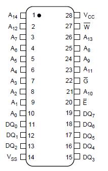
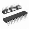
Features: · Fast Access Times: 20/25 ns· Low-Power Standby when Deselected· TTL Compatible I/O· 5 V ± 10% Supply· Fully-Static Operation· JEDEC Standard Pinout· Packages: 28-Pin, 300-mil DIP 28-Pin, 300-mil SOJPinoutSpecifications PARAMETER RATING VCC to VSS Potential 0.5 V to 7 V I...
LH52258A: Features: · Fast Access Times: 20/25 ns· Low-Power Standby when Deselected· TTL Compatible I/O· 5 V ± 10% Supply· Fully-Static Operation· JEDEC Standard Pinout· Packages: 28-Pin, 300-mil DIP 28-Pin,...
SeekIC Buyer Protection PLUS - newly updated for 2013!
268 Transactions
All payment methods are secure and covered by SeekIC Buyer Protection PLUS.
· Fast Access Times: 20/25 ns
· Low-Power Standby when Deselected
· TTL Compatible I/O
· 5 V ± 10% Supply
· Fully-Static Operation
· JEDEC Standard Pinout
· Packages:
28-Pin, 300-mil DIP
28-Pin, 300-mil SOJ
PARAMETER | RATING |
VCC to VSS Potential | 0.5 V to 7 V |
Input Voltage Range | 0.5 V to VCC + 0.5 V |
DC Output Current 2 | ± 40 mA |
Storage Temperature Range | 65° to 150 |
Power Dissipation (Package Limit) | 1.0 W |
The LH52258A is a high-speed 262,144 bit static RAM organized as 32K×8. A fast, efficient design is obtained with a CMOS periphery and a matrix constructed with polysilicon load memory cells.
This LH52258A is fully static in operation. The Chip Enable (E) control permits Read and Write operations when active (LOW) or places the RAM in a low-power standby mode when inactive (HIGH). Standby power (ISB1) drops to its lowest level if E is raised to within 0.2 V of VCC.
Write cycles occur when both Chip Enable (E) and Write Enable (W) are LOW. Data is transferred from the DQ pins to the memory location specified by the 15 address lines. The proper use of the Output Enable control (G) can prevent bus contention.
When E is LOW and W is HIGH, a static Read will occur at the memory location specified by the address lines. G must be brought LOW to enable the outputs. Since the device is fully static in operation, new Read cycles can be performed by simply changing the address.
High-frequency design techniques should be employed to obtain the best performance from this device. Solid, low-impedance power and ground planes, with high-frequency decoupling capacitors, are recommended. Series termination of the inputs should be considered when transmission line effects occur.