Product
:
Mounting Style
: SMD/SMT
Packaging
: Tube
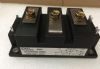
Package / Case
: PowerSO-20
Operating Supply Voltage
: 8 V to 17 V
Type
: Folder Actuator
Supply Current
: 100 uA to 200 uA
Features: ·BIDIRECTIONAL SWITCH
·MOTOR STOP CONTROLLED BY MOTOR CURRENT
·START UP AND END CURRENT DETECTION THRESHOLDS PROGRAMMABLE WITH EXTERNAL RSHUNT
·STOP DELAY TIME FOR START UP AND END PHASE PROGRAMMABLE WITH EXTERNAL RC
·OUTPUT SHORT CIRCUIT PROTECTION
·OUTPUT CURRENT LIMITING > 8A
·THERMAL PROTECTION
·ACTIVE DIODE BRIDGE INTERNALLY DIFFUSED
·MAXIMUMVOLTAGE SUPPLY 50V
·TECHNOLOGY MULTIPOWER BCD60II
Pinout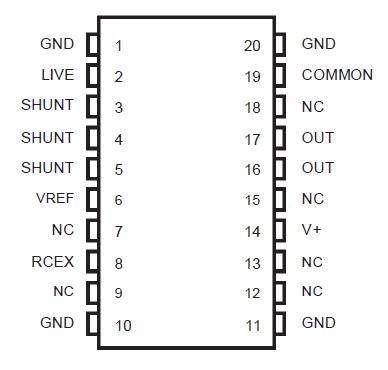 Specifications
| Symbol |
Parameter |
Value |
Unit |
| Vbat |
Supply Voltage |
50 |
V |
| Iout |
Output current DC
at Is |
5
6 |
A
A |
| Top |
Operating Temperature |
-40 to 125 |
°C |
DescriptionThis L9639 typically drives a direct current motor servomechanism providing two extreme end positions and replaces end position switches or sensors.
For more details see the Timing diagram (Fig. 1) and the Application diagram (Fig. 2)
When the power supply is applied, or its polarity is inverted the motor is powered up (start point). The current of the L9639 eaches the start up value near to the stall current, always higher than the threshold value of the device (ITH) . A delay on the detection (TD) permits the motor start up and the consequentdecrease of the current.|
During the free running phase, the current in the motor must always be lower the threshold ITH. When the L9639 reaches the end of the run limit, the current increases reaching a value that, depending on the application, can be the stall value or can depend on some torque limiting friction (end point). Provided that this value is higher the programmed threshold ITH , the L9639 is stopped after a time delay TD, and the device goes into a low consumption standby status, ready to restart the motor for a new cycle if the polarity of the power supply is inverted (or power is switched off and on).
In any case, if the current exceeds the higher threshold ITHCC, the L9639 is immediately stopped because a short circuit is detected. The delay TD consists of two DMOS transistors connected in series with common drain to act as a switch with the voltage applied in both direction. A charge pump takes the gates of the DMOS above the also permits the motor to overcome some small obstacle during the free run.
The threshold current for the running phase ITH is obtained by comparing the voltage on an external sensing resistor (RSHUNT) to a threshold voltage VTH.
1) ITH = VTH / RSHUNT
VTH is constant in respect to the power supply voltage because in most applications, the end of run current is depending only on motor and the mechanic torque limiting device (friction current). The threshold current for the short circuit detection is:
2) ITHCC = VTHCC/RSHUNT @VTHCC = 330mV@ Vbat = 12V
and depends intentionally on the supply voltage because of the same dependenceof the stall current. The time TD depends on two external components, capacitor CEX and resistor REX. TD is obtained by the following expression :
TD = REX . REX . KTD
KTD is a constant typically of unit value.
The block diagram is shown on the first page. The change of the polarity between pins COMMON and LIVE, needs the active bridge to supply the internal circuit. The internal supply voltage is available between pins V+ and GND and a storage and filter capacitor (100nF) must be connected between these pins. The output stage supply voltage. The motor is controlled by the control 'logic low voltage' block that receives the motor status for the comparator. The 'charge CEX' block controls the TD delay.
Parameters: | Technical/Catalog Information | L9639 |
| Vendor | STMicroelectronics |
| Category | Integrated Circuits (ICs) |
| Applications | DC Motor Controller |
| Number of Outputs | 1 |
| Voltage - Supply | 8 V ~ 17 V |
| Voltage - Load | - |
| Current - Output | - |
| Operating Temperature | -40°C ~ 125°C |
| Package / Case | PowerSO-20 Exposed Bottom Pad |
| Packaging | Tube |
| Drawing Number | * |
| Lead Free Status | Lead Free |
| RoHS Status | RoHS Compliant |
| Other Names | L9639
L9639
|
 L9639 Data Sheet