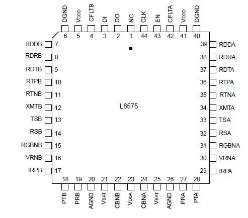
L8575

Features: ` Two channels in a single package` Serial data interface` Per-channel powerdown` Low standby power (65 mW per channel)` Integrated protection` No external protection device required` Battery noise cancellation` Switchhook detector` Ring-trip detector` Switchhook and ring-trip detector s...

product image

L8575 Picture
SeekIC No. : 004389594 Detail

L8575: Features: ` Two channels in a single package` Serial data interface` Per-channel powerdown` Low standby power (65 mW per channel)` Integrated protection` No external protection device required` Batt...

floor Price/Ceiling Price

Part Number:
L8575
Supply Ability:
5000

Price Break

  • Qty
  • 1~5000
  • Unit Price
  • Negotiable
  • Processing time
  • 15 Days
Total Cost: $ 0.00

SeekIC Buyer Protection PLUS - newly updated for 2013!

  • Escrow Protection.
  • Guaranteed refunds.
  • Secure payments.
  • Learn more >>

Month Sales

268 Transactions

Rating

evaluate  (4.8 stars)

Upload time: 2025/1/11

Payment Methods

All payment methods are secure and covered by SeekIC Buyer Protection PLUS.

Notice: When you place an order, your payment is made to SeekIC and not to your seller. SeekIC only pays the seller after confirming you have received your order. We will also never share your payment details with your seller.
Product Details

Description


Features:

` Two channels in a single package
` Serial data interface
` Per-channel powerdown
` Low standby power (65 mW per channel)
` Integrated protection
` No external protection device required
` Battery noise cancellation
` Switchhook detector
` Ring-trip detector
` Switchhook and ring-trip detector self-test
` Fault detector
` Zero ring voltage cross detection
` Three relay drivers per channel
`44-pin, surface-mount, plastic package (PLCC)


Application

· Per-channel ring-trip detectors, loop closure detectors.
· Six relay drivers (three per channel).
· 8-bit serial-to-parallel and parallel-to-serial logic interface.
· Per-channel circuits which eliminate the battery noise that is coupled to the Tip and Ring through the dc feed resistors.
· Fault detection.
· Zero ring voltage detection.


Pinout

  Connection Diagram


Specifications

Stresses in excess of the absolute maximum ratings can cause permanent damage to the device. These are absolute
stress ratings only. Functional operation of the device is not implied at these or any other conditions in excess of those given in the operational sections of this data sheet. Exposure to absolute maximum ratings for extended periods can adversely affect device reliability.

Parameter Symbol Min Value Max Unit
5 V Analog dc Supply VDDA 0.5 - +7.0 V
5 V Digital dc Supply VDDD 0.5 - +7.0 V
Office Battery Supply VBAT 65 - +0.5 V
Logic Input Voltage - 0.5 - VDDD + 0.5 V
Logic Input Clamp Diode Current, per Pin - - ±20 - mA
Logic Output Voltage - 0.5 - VDDD + 0.5 V
Logic Output Current, per Pin (excluding relay drivers) - - ±35 - mA
Maximum Junction Temperature - - 150 - °C
Operating Temperature Range - 40 - +125 °C
Storage Temperature Range Tstg 40 - +125 °C
Relative Humidity Range - 5 - 95 %
Ground Potential Difference (DGND to AGND) - +0.5 - 0.5 V


Notes:
Analog and battery voltages are referenced to AGND; digital (logic) voltages are referenced to DGND.

The IC can be damaged unless all ground connections are applied before, and removed after, all other connections. Furthermore, when powering the device, the user must guarantee that no external potential creates a voltage on any pin of the device that exceeds the device ratings. Some of the known examples of conditions that cause such potentials during powering are (1) an inductor connected to Tip and Ring that can force an overvoltage on VBAT through external components if the VBAT connection chatters, and (2) inductance in the VBAT lead that could resonate with the VBAT filter capacitor to cause a destructive overvoltage.


Description

The L8575 is a dual-resistive, low-cost subscriber line interface circuit (SLIC) that is optimized to meet both ITU-T recommendations and LSSGR requirements for 600 /900  resistive and complex impedance termination applications. It interfaces the lowvoltage circuits on an analog line card to the Tip and Ring of two subscriber loops. The L8575 does not supply dc current to the subscriber loops-external resistors are used for this purpose. The device is built using a 90 V complementary bipolar (CBIC) process and is available in a 44-pin PLCC package.


Customers Who Bought This Item Also Bought

Margin,quality,low-cost products with low minimum orders. Secure your online payments with SeekIC Buyer Protection.
Potentiometers, Variable Resistors
RF and RFID
Resistors
Circuit Protection
Optical Inspection Equipment
View more