Features: • Four potentiometers in one package
• 256 resistor taps - 0.4% resolution
• I2C serial interface
• Wiper resistance: 70 typical @ 3.3V
• Standby current <5A max
• Power supply: 2.7V to 5.5V
• 50k, 10k total resistance
• 14 Lead TSSOP
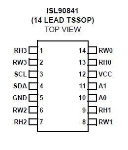
• Pb-free plus anneal available (RoHS compliant)Pinout
SpecificationsAbsolute Maximum Ratings
Storage temperature . . . . . . . . . . . . . . . . . . . . . .-65°C to +150°C
Voltage at any digital interface pin
with respect to GND . . . . . . . . . . . . . . . . . . . . . . . . -0.3V to VCC+0.3
VCC . . . . . . . . . . . . . . . . . . . . . . . . . . . . . . . . . . . . . . . . -0.3V to +6V
Voltage at any DCP pin with
respect to GND. . . . . . . . . . . . . . . . . . . . . . . . . . . . . . .. -0.3V to VCC
Lead temperature (soldering, 10s). . . . . . . . . . . . . . . . . . .. 300°C
IW (10s) . . . . . . . . . . . . . . . . . . . . . . . . . . . . . . . . . . . . . . . ±6mA
Latchup . . . . . . . . . . . . . . . . . . . . . . . . . . Class II, Level B at +85°C
ESD . . . . . . . . . . . . . . . . . . . . . . . . . . . . . . .>2kV Human Body Model
DescriptionEach DCP is implemented with a combination of resistor elements and CMOS switches. The physical ends of each DCP are equivalent to the fixed terminals of a mechanical potentiometer (RH and RL pins). The RW pin of each DCP is connected to intermediate nodes, and is equivalent to the wiper terminal of a mechanical potentiometer. The position of the wiper terminal within the DCP is controlled by an 8-bit volatile Wiper Register (WR). Each DCP has its own WR. When the WR of a DCP contains all zeroes (WR<7:0>: 00h),its wiper terminal (RW) is closest to its "Low" terminal (RL). When the WR of a DCP contains all ones (WR<7:0>: FFh),its wiper terminal (RW) is closest to its "High" terminal (RH).As the value of the WR increases from all zeroes (00h) to allones (255 decimal), the wiper moves monotonically from the position closest to RL to the closest to RH.
At the same time,the resistance between RW and RL increases monotonically,while the resistance between RH and RW decreases monotonically. While the ISL90840 is being powered up, all four WRs are reset to 80h (128 decimal), which locates RW roughly at the center between RL and RH.The WRs can be read or written to directly using the I2C serial interface as described in the following sections. The I2C interface Address Byte has to be set to 00h, 01h, 02h,and 03h to access the WR of DCP0, DCP1, DCP2, and DCP3 respectively

 ISL90841 Data Sheet


