IRF440

Features: • 8A, 500V• rDS(ON) = 0.850W• Single Pulse Avalanche Energy Rated• SOA is Power-Dissipation Limited• Nanosecond Switching Speeds• Linear Transfer Characteristics• High Input Impedance• Majority Carrier Device• Related Literature - TB3...

product image

IRF440 Picture
SeekIC No. : 004376488 Detail

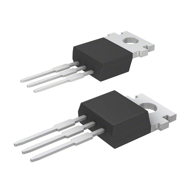
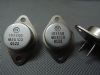
IRF440: Features: • 8A, 500V• rDS(ON) = 0.850W• Single Pulse Avalanche Energy Rated• SOA is Power-Dissipation Limited• Nanosecond Switching Speeds• Linear Transfer Charac...

floor Price/Ceiling Price

Part Number:
IRF440
Supply Ability:
5000

Price Break

  • Qty
  • 1~5000
  • Unit Price
  • Negotiable
  • Processing time
  • 15 Days
Total Cost: $ 0.00

SeekIC Buyer Protection PLUS - newly updated for 2013!

  • Escrow Protection.
  • Guaranteed refunds.
  • Secure payments.
  • Learn more >>

Month Sales

268 Transactions

Rating

evaluate  (4.8 stars)

Upload time: 2024/5/29

Payment Methods

All payment methods are secure and covered by SeekIC Buyer Protection PLUS.

Notice: When you place an order, your payment is made to SeekIC and not to your seller. SeekIC only pays the seller after confirming you have received your order. We will also never share your payment details with your seller.
Product Details

Description


Features:

• 8A, 500V
• rDS(ON) = 0.850W
• Single Pulse Avalanche Energy Rated
• SOA is Power-Dissipation Limited
• Nanosecond Switching Speeds
• Linear Transfer Characteristics
• High Input Impedance
• Majority Carrier Device
• Related Literature - TB334 "Guidelines for Soldering Surface Mount Components to PC Boards"


Pinout

                                                                                                             IRF440                   UNITS
Drain To Source Voltage (Note 1) . . . . . . . . . .  . . . . . . . . . . VDS         500 V                      V
Drain To Gate Voltage (RGS = 20kW)  . . . . . . . . . . . . . . . . VDGR         500 V                      V
Continuous Drain Current . . . . . . . . . . . . . . . . . . . . . . . . . . . ID            8.0                        A
TC = 100oC . . . . . . . . . . . . . . . . . . . . . . . . . . . . . . . . . . . . . . ID            5.0                        A
Pulsed Drain Current (Note 3) . . . . . . . . .  . . . . . . . . . . . IDM 32 A          32                       A       
Gate To Source Voltage . . . . . . . . . . . . .  . . . . . . . . . .  . VGS ±20 V     ±20                       V                
Maximum Power Dissipation . . . . . . . . . . . . . . . . . . . . . . PD 125 W        125                     W                 
Linear Derating Factor . . . . . . . .. . . . . . . . . . . . . . . . . . . 1.0 W/oC        1.0                     W/oC
Single Pulse Avalanche Energy Rating (Note 4) . .  . . . .. . EAS 510 A      510                      A               
Operating and Storage Temperature . . . . . . .TJ, TSTG -55 to 150 oC     -55 to 150           oC                            
Maximum Temperature for Soldering
Leads at 0.063in (1.6mm) from Case for 10s. . . . . . . . . .. . . . . . .TL          300                  oC                    
Package Body for 10s, See Techbrief 334 . . . . . . . . . . . . . . . . . Tpkg          260                 oC                      

CAUTION: Stresses above those listed in "Absolute Maximum Ratings" may cause permanent damage to the device. This is a stress only rating and operation of the device at these or any other conditions above those indicated in the operational sections of this specification is not implied.
NOTE:1. TJ = 25oC to 125oC.


Specifications

IRF440 UNITS
Drain To Source Voltage (Note 1) . . . . . . . . . . . . . . . . . . . . VDS 500 V V
Drain To Gate Voltage (RGS = 20kW) . . . . . . . . . . . . . . . . VDGR 500 V V
Continuous Drain Current . . . . . . . . . . . . . . . . . . . . . . . . . . . ID 8.0 A
TC = 100oC . . . . . . . . . . . . . . . . . . . . . . . . . . . . . . . . . . . . . . ID 5.0 A
Pulsed Drain Current (Note 3) . . . . . . . . . . . . . . . . . . . . IDM 32 A 32 A
Gate To Source Voltage . . . . . . . . . . . . . . . . . . . . . . . . VGS ±20 V ±20 V
Maximum Power Dissipation . . . . . . . . . . . . . . . . . . . . . . PD 125 W 125 W
Linear Derating Factor . . . . . . . .. . . . . . . . . . . . . . . . . . . 1.0 W/oC 1.0 W/oC
Single Pulse Avalanche Energy Rating (Note 4) . . . . . .. . EAS 510 A 510 A
Operating and Storage Temperature . . . . . . .TJ, TSTG -55 to 150 oC -55 to 150 oC
Maximum Temperature for Soldering
Leads at 0.063in (1.6mm) from Case for 10s. . . . . . . . . .. . . . . . .TL 300 oC
Package Body for 10s, See Techbrief 334 . . . . . . . . . . . . . . . . . Tpkg 260 oC

CAUTION: Stresses above those listed in "Absolute Maximum Ratings" may cause permanent damage to the device. This is a stress only rating and operation of the device at these or any other conditions above those indicated in the operational sections of this specification is not implied.
NOTE:1. TJ = 25oC to 125oC.


Customers Who Bought This Item Also Bought

Margin,quality,low-cost products with low minimum orders. Secure your online payments with SeekIC Buyer Protection.
Cables, Wires - Management
Boxes, Enclosures, Racks
Motors, Solenoids, Driver Boards/Modules
Tapes, Adhesives
803
View more