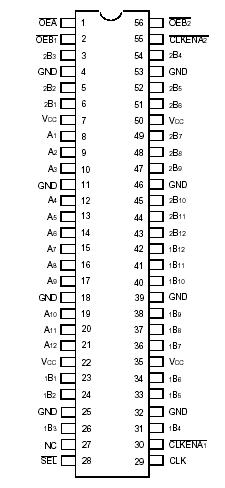
Features: • ESD > 2000V per MIL-STD-883, Method 3015; > 200V using machine model (C = 200pF, R = 0)• 1.8V Optimized• 0.8V to 2.7V Operating Range• Inputs/outputs tolerant up to 3.6V• Output drivers: ±9mA @ 2.3V• Supports hot insertion• Available in T...
IDT74AUC16373: Features: • ESD > 2000V per MIL-STD-883, Method 3015; > 200V using machine model (C = 200pF, R = 0)• 1.8V Optimized• 0.8V to 2.7V Operating Range• Inputs/outputs tolera...
SeekIC Buyer Protection PLUS - newly updated for 2013!
268 Transactions
All payment methods are secure and covered by SeekIC Buyer Protection PLUS.
Description |
Symbol |
Max |
unit |
Terminal Voltage with Respect to GND |
VTERM(2) |
0.5 to +4.6
|
V |
Terminal Voltage with Respect to GND |
VTERM(3)
|
0.5 to VCC+0.5 |
V |
Storage Temperature |
TSTG |
65 to +150
|
° C |
DC Output Current |
IOUT
|
50 to +50 |
mA |
Continuous Clamp Current, VI < 0 or VI > VCC |
IIK |
±50
|
mA |
Continuous Clamp Current, VO < 0 |
IOK |
50 |
mA |
Continuous Current through each VCC or GND |
ICC ISS |
±100 |
mA |
NOTES:
1. Stresses greater than those listed under ABSOLUTE MAXIMUM RATINGS may cause permanent damage to the device. This is a stress rating only and functional operation of the device at these or any other conditions above those indicated in the operational sections of this specification is not implied. Exposure to absolute maximum rating conditions for extended periods may affect reliability.
This 16-bit transparent D-type latch is built using advanced CMOS technology. IDT74AUC16373 can be used as a single 16-bit latch or as two 8-bit latches. When the latch enable (LE) input is high, the Q outputs follow the data (D) inputs. When LE is taken low, the Q outputs are latched at the levels set up at the D inputs.
A buffered output enable (OE)IDT74AUC16373 input can be used to place the eight outputs in either a normal logic state (high or low logic levels) or a high-impedance state. In the high-impedance state, the outputs neither load nor drive the bus lines significantly. The OE input does not affect the internal operation of the latch. IDT74AUC16373 is fully specified for partial power-down applications using IOFF.
The IOFF circuitry disables the outputs, preventing damaging current backflow through IDT74AUC16373 when it is powered down. To ensure the high-impedance state during power up or power down, OE IDT74AUC16373 should be tied to VDD through a pull-up resistor; the minimum value of the resistor is determined by the current-sinking capability of the driver.