IDT74ALVCH16903

Features: • 0.5 MICRON CMOS Technology• Typical tSK(o) (Output Skew) < 250ps• ESD > 2000V per MIL-STD-883, Method 3015; > 200V using machine model (C = 200pF, R = 0)• VCC = 3.3V ± 0.3V, Normal Range• VCC = 2.7V to 3.6V, Extended Range• VCC = 2.5V ± 0.2V...

product image

IDT74ALVCH16903 Picture
SeekIC No. : 004372791 Detail

IDT74ALVCH16903: Features: • 0.5 MICRON CMOS Technology• Typical tSK(o) (Output Skew) < 250ps• ESD > 2000V per MIL-STD-883, Method 3015; > 200V using machine model (C = 200pF, R = 0)•...

floor Price/Ceiling Price

Part Number:
IDT74ALVCH16903
Supply Ability:
5000

Price Break

  • Qty
  • 1~5000
  • Unit Price
  • Negotiable
  • Processing time
  • 15 Days
Total Cost: $ 0.00

SeekIC Buyer Protection PLUS - newly updated for 2013!

  • Escrow Protection.
  • Guaranteed refunds.
  • Secure payments.
  • Learn more >>

Month Sales

268 Transactions

Rating

evaluate  (4.8 stars)

Upload time: 2024/11/21

Payment Methods

All payment methods are secure and covered by SeekIC Buyer Protection PLUS.

Notice: When you place an order, your payment is made to SeekIC and not to your seller. SeekIC only pays the seller after confirming you have received your order. We will also never share your payment details with your seller.
Product Details

Description


Features:

• 0.5 MICRON CMOS Technology
• Typical tSK(o) (Output Skew) < 250ps
• ESD > 2000V per MIL-STD-883, Method 3015; > 200V using machine model (C = 200pF, R = 0)
• VCC = 3.3V ± 0.3V, Normal Range
• VCC = 2.7V to 3.6V, Extended Range
• VCC = 2.5V ± 0.2V
• CMOS power levels (0.4µ W typ. static)
• Rail-to-Rail output swing for increased noise margin
• Available in SSOP, TSSOP, and TVSOP packages


Application

• 3.3V high speed systems
• 3.3V and lower voltage computing systems


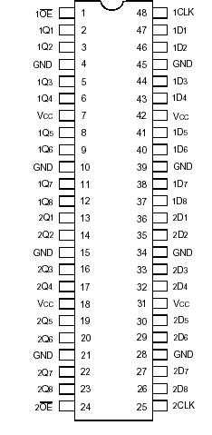
Pinout

  Connection Diagram


Specifications

Description
Symbol
Max
unit
Terminal Voltage with Respect to GND
VTERM(2)
0.5 to +4.6
V
Terminal Voltage with Respect to GND
VTERM(3)
0.5 to VCC+0.5
V
Storage Temperature
TSTG
65 to +150
° C
DC Output Current
IOUT
50 to +50
mA
Continuous Clamp Current,
VI < 0 or VI > VCC
IIK
±50
mA
Continuous Clamp Current, VO < 0
IOK
50
mA
Continuous Current through each
VCC or GND
ICC
ISS
±100
mA


NOTES:
1. Stresses greater than those listed under ABSOLUTE MAXIMUM RATINGS may cause permanent damage to the device. This is a stress rating only and functional operation of the device at these or any other conditions above those indicated in the operational sections of this specification is not implied. Exposure to absolute maximum rating conditions for extended periods may affect reliability.
2. VCC terminals.
3. All terminals except VCC.


Description

This 12-bit universal bus driver of the IDT74ALVCH16903 is built using advanced dual metal CMOS technology. This device has dual outputs and can operate as a buffer or an edge-triggered register. In both modes, parity is checked on APAR, which arrives one cycle after the data to which it applies. The YERR output, which is produced one cycle after APAR, is open drain. MODE selects one of the two data paths. When MODE is low, the device operates as an edge-triggered register.

On the positive transition of the clock (CLK) input and when the clock-enable (CLKEN) input of the IDT74ALVCH16903 is low, data setup at the A inputs is stored in the internal registers. On the positive transition of CLK and when CLKEN is high, only data setup at the 9A-12A inputs is stored in their internal registers. When MODE is high, the device operates as a buffer and data at the A inputs passes directly to the outputs.

The 11A/YERREN of the IDT74ALVCH16903 serves a dual purpose; it acts as a normal data bit and also enables YERR data to be clocked into the YERR output register. When used as a single device, parity output enable (PAROE) must be tied high; when parity input/output (PARI/O) is low, even parity is selected and when PARI/O is high, odd parity is selected. When used in pairs and PAROE is low, the parity sum is output on PARI/O for cascading to the second ALVCH16903.

When used in pairs and PAROE is high, PARI/O accepts a partial parity sum from the first ALVCH16903. A buffered output-enable (OE) input can be used to place the 24 outputs and YERR in either a normal logic state (high or low logic levels) or a high-impedance state. In the high-impedance state, the outputs neither load nor drive the bus lines significantly.

The high-impedance state and increased drive provide the capability to drive bus lines without need for interface or pullup components.

The IDT74ALVCH16903has been designed with a ±24mA output driver. This driver is capable of driving a moderate to heavy load while maintaining speed performance.


Customers Who Bought This Item Also Bought

Margin,quality,low-cost products with low minimum orders. Secure your online payments with SeekIC Buyer Protection.
Computers, Office - Components, Accessories
Boxes, Enclosures, Racks
Prototyping Products
DE1
Soldering, Desoldering, Rework Products
Power Supplies - External/Internal (Off-Board)
Power Supplies - Board Mount
View more