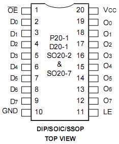
Features: `0.5 MICRON CMOS Technology`ESD > 2000V per MIL-STD-883, Method 3015; > 200V using machine model (C = 200pF, R = 0)`25 mil Center SSOP Packages`Extended commercial range of -40 to +85`VCC = 3.3V ?0.3V, Normal Range or VCC = 2.7V to 3.6V, Extended Range`CMOS power levels (0.4W typ. ...
IDT54FCT3573PYB: Features: `0.5 MICRON CMOS Technology`ESD > 2000V per MIL-STD-883, Method 3015; > 200V using machine model (C = 200pF, R = 0)`25 mil Center SSOP Packages`Extended commercial range of -40 to +8...
SeekIC Buyer Protection PLUS - newly updated for 2013!
268 Transactions
All payment methods are secure and covered by SeekIC Buyer Protection PLUS.
Features: • IDT54/74FCT646 equivalent to FAST™speed;• IDT54/74FCT646A 30% faster...
Symbol | Rating | Commercial | Military | Unit |
VTERM(2) | Terminal Voltagewith Respect toGND | -0.5 to +4.6 | -0.5 to +4.6 | V |
VTERM(3) | Terminal Voltagewith Respect toGND | -0.5 to +7.0 | -0.5 to +7.0 | V |
VTERM(4) | Terminal Voltagewith Respect toGND | -0.5 to to VCC + 0.5 | -0.5 to VCC + 0.5 | V |
TA | Operating Temperature | -40 to +85 | -55 to +125 | |
TBIAS | Temperature Under Bias | -55 to +125 | -65 to +135 | |
TSTG | Storage Temperature | -55 to +125 | -65 to +150 | |
PT | Power Dissipation | 1.0 | 1.0 | W |
IOUT | DC Output Current | -60 to +60 | -60 to +60 | mA |
NOTES: 3093 lnk 03
1.Stresses greater than those listed under ABSOLUTE MAXIMUM RAT- INGS may cause permanent damage to the device. This is a stress rating only and functional operation of the device at these or any other conditions above those indicated in the operational sections of this specification is not implied. Exposure to absolute maximum rating conditions for ex- tended periods may affect reliability.
2.Vcc terminals.
3.Input terminals.
4.Output and I/O terminals.
The IDT54FCT3573PYB are octal transparent latches built using an advanced dual metal CMOS technology.
These octal latches have 3-state outputs and are intended for bus oriented applications. The flip-flops appear transpar- ent to the data when Latch Enable (LE) is HIGH. When LE of the IDT54FCT3573PYB is LOW, the data that meets the set-up time is latched. Data appears on the bus when the Output Enable () is LOW. When is HIGH, the bus output is in the high-impedance state.