Features: • A, B, C and D speed grades• Low input and output leakage £1mA (max.)• CMOS power levels• True TTL input and output compatibility VOH = 3.3V (typ.) VOL = 0.3V (typ.)• High drive outputs (-15mA IOH, 48mA IOL)• Meets or exceeds JEDEC standard 18...
IDT29FCT520BT: Features: • A, B, C and D speed grades• Low input and output leakage £1mA (max.)• CMOS power levels• True TTL input and output compatibility VOH = 3.3V (typ.) VOL = 0...
SeekIC Buyer Protection PLUS - newly updated for 2013!
268 Transactions
All payment methods are secure and covered by SeekIC Buyer Protection PLUS.
Symbol | Rating | Commercial | Military | Unit |
VTERM | Terminal Voltage with Respect to GND |
-0.5 to +7.0 | -0.5 to +7.0 | V |
VTERM(3) |
Terminal Voltage |
0.5 to |
0.5 to |
V |
TA | Operating Temperature |
0 to +70 | -55 to +125 | |
TBIAS | Temperature Under Bias |
-55 to +125 | -65 to +135 | |
TSTG | Storage Temperature |
-55 to +125 | -65 to +150 | |
PT |
Power Dissipation |
0.5 |
0.5 |
W |
IOUT | DC Output Current |
60 to +120 | 60 to +120 | mA |
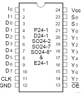
The IDT29FCT520BT each contain four 8-bit positive edge-triggered registers. These may be operated as a dual 2-level or as a single 4-level pipeline. A single 8-bit input is provided and any of the four registers is available at the 8-bit, 3-state output.
These devices differ only in the way data is loaded into and between the registers in 2-level operation. The difference is illustrated in Figure 1. In the IDT29FCT520BT when data is entered into the first level (I = 2 or I = 1), the existing data in the first level is moved to the second level. In the IDT29FCT520BT, these instructions simply cause the data in the first level to be overwritten. Transfer of data to the second level is achieved using the 4-level shift instruction (I = 0). This transfer also causes the first level to change. In either part I=3 is for hold.