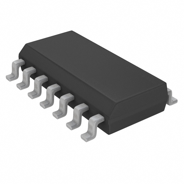
Features: • Industrial range available (40°C to +85°C)• Multifunction capability• Non-inverting data path• 3-State outputs• See 74F258A for inverting versionPinoutSpecifications(Operation beyond the limits set forth in this table may impair the useful life of the devi...
I74F257AD: Features: • Industrial range available (40°C to +85°C)• Multifunction capability• Non-inverting data path• 3-State outputs• See 74F258A for inverting versionPinoutSpeci...
SeekIC Buyer Protection PLUS - newly updated for 2013!
268 Transactions
All payment methods are secure and covered by SeekIC Buyer Protection PLUS.
(Operation beyond the limits set forth in this table may impair the useful life of the device. Unless otherwise noted these limits are over the operating free-air temperature range.)
SYMBOL |
PARAMETER |
RATING |
UNIT | |
VCC |
Supply voltage |
0.5 to +7.0 |
V | |
VIN |
Input voltage |
0.5 to +7.0 |
V | |
IIN |
Input current |
30 to +5 |
mA | |
VOUT |
Voltage applied to output in High output state |
0.5 to VCC |
V | |
IOUT |
Current applied to output in Low output state |
48 |
mA | |
Tamb |
Operating free air temperature range | Commercial range |
0 to +70 |
|
Industrial range |
40 to +85 |
|||
Tstg |
Storage temperature range |
65 to +150 |
The I74F257AD has four identical 2-input multiplexers with 3-State outputs which select 4 bits of data from two sources uncer control of a common Select (S) input. The I0a inputs are selected when the common Select input is Low and the I1n inputs are selected when the common Select input is High. Data appears at the outputs in true non-inverted form from the selected inputs. The I74F257AD is the logic implementation of a 4-pole, 2-position switch where the position of the switch is determined by the logic levels supplied to the common Slect input. Outputs are forced to a high impedance "off" state when the Output Enable (OE) is High. All but one device must be in high impedance state to avoid currents that would exceed the maximum rating if the outputs were tied together. Design of the Output Enable signals must ensure that there is no overlap when outputs of 3-state devices were tied together.