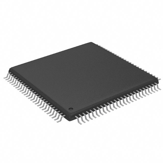
Features: • High-speed H8/300H central processing unit with an internal 16-bit architecture
- Upward-compatible with H8/300 CPU on an object level
- Sixteen 16-bit general registers
- 62 basic instructions
• Various peripheral functions
- RTC (can be used as a free-running counter)
- Asynchronous event counter (AEC)
- Timer B1
- Timer W
- Watchdog timer
- SCI (asynchronous or clock synchronous serial communication interface)
- SSU (synchronous serial communication unit)*
- I2C bus interface (conforms to the I2C bus interface format that is advocated by Philips Electronics)*
- 10-bit A/D converter
- Comparators
Note: * SSU and IIC2 are shared
Specifications
| Item |
Symbol |
Value |
Unit |
Note |
| Power supply voltage |
VCC |
0.3 to +4.3 |
V |
*1 |
| Analog power supply voltage |
AVCC |
0.3 to +4.3 |
V |
|
| Input voltage |
Other than port B |
VIN |
0.3 to VCC +0.3 |
V |
|
| Port B |
AVin |
0.3 to AVCC +0.3 |
V |
|
| Operating temperature |
Topr |
20 to +75
(general
specifications)*2 |
|
|
40 to +85
(wide temperature
range
specifications)*2 |
|
| Storage temperature |
Tstg |
55 to +125 |
|
|
Notes: 1. Permanent damage may occur to the LSI if absolute maximum ratings are exceeded. Normal operation should be under the conditions specified in Electrical Characteristics. Exceeding these values can result in incorrect operation and reduced reliability.
2. The operating temperature range for flash memory programming/erasing is Ta = 0 to +75°C.
DescriptionThe HD64F38602R features:
1. When the BSET instruction is executed, first the CPU reads port 5. Since P57 and P56 are input pins, the CPU reads the pin states (low-level and high-level input). P55 to P50 are output pins, so the CPU reads the value in PDR5. In this example PDR5 has a value of H'80, but the value read by the CPU is H'40.
2. Next, the CPU sets bit 0 of the read data to 1, changing the PDR5 data to H'41.
3. Finally, the CPU writes H'41 to PDR5, completing execution of BSET instruction.

 HD64F38602R Data Sheet


