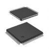
Features: SpecificationsDescription The HD613901(LCD-IV) has the following features including 4-bit architecture;4,096 words of program ROM(10 bit/word);256 digits of data RAM and display data RAM(4 bits/digit);control circuit and direct drive circuit for LCD;Timer/event counter etc. The hybrid of...
HD613901(LCD-IV): Features: SpecificationsDescription The HD613901(LCD-IV) has the following features including 4-bit architecture;4,096 words of program ROM(10 bit/word);256 digits of data RAM and display data RAM(4...
SeekIC Buyer Protection PLUS - newly updated for 2013!
268 Transactions
All payment methods are secure and covered by SeekIC Buyer Protection PLUS.
The HD613901(LCD-IV) has the following features including 4-bit architecture;4,096 words of program ROM(10 bit/word);256 digits of data RAM and display data RAM(4 bits/digit);control circuit and direct drive circuit for LCD;Timer/event counter etc.
The hybrid of HD613901(LCD-IV) performs 2 wire to 4 wire conversion by taking the 4 wire signal from an analog switch or voice CODEC, a.c. coupled to VRIN, and converting it to a 2 wire differential signal at tip and ring. The 2 wire signal applied to tip and ring by the telephone is converted to a 4 wire signal and should be a.c. coupled to Vx which is the output from the SLIC to the analog switch or voice CODEC input.The ADM70x family of products is guaranteed to provide a valid reset level with VCC as low as 1 V; please refer to the Typi- cal Performance Characteristics. As VCC drops below 1 V, the internal transistor will not have sufficient drive to hold it ON so the voltage on RESET will no longer be held at 0 V. A pull-down resistor as shown in Figure 7 may be connected externally to hold the line low if it is required.
A typical HD613901(LCD-IV) single video channel connection diagram for the MSK 620 is shown in Figure 1 above. The DC voltage at pin 6 is internally fixed at +2.6V and the video signal is AC coupled to the input. An internal reference voltage generator supplies a +5.0VDC level at pin 9 for use with the contrast, drive and brightness control potentiometers. With pin 7 at 0V, minimum gain is realized. With pin 7 at 4V, maximum gain is realized. The clamp gate input at pin 11 accepts a TTL level clamp signal for DC restoration during the back porch segment of the video signal. Pin 17 is the brightness control input pin and accepts a zero to four volt DC level.
Stresses above those listed under Absolute Maximum Ratings of HD613901(LCD-IV) may cause permanent damage to the device. This is a stress rating only and functional operation of the device at these or any other condition s above those indicated in the operational section of this specification is not implied. Exposure to absolute maximum rating conditions for extended periods may affect device reliability.