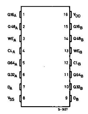
PinoutSpecifications Symbol Parameter Value Unit VDD* Supply Voltage :HCC TypesHCF Types 0.5 to + 20 0.5 to + 18 VV Vi Input Voltage 0.5 to VDD + 0.5 V II DC Input Current (any one input) ± 10 mA Pt ot Total Power Dissipation (per packa...
HCC/HCF4517B: PinoutSpecifications Symbol Parameter Value Unit VDD* Supply Voltage :HCC TypesHCF Types 0.5 to + 20 0.5 to + 18 VV Vi Input Voltage 0.5 to VDD + 0.5 V ...
SeekIC Buyer Protection PLUS - newly updated for 2013!
268 Transactions
All payment methods are secure and covered by SeekIC Buyer Protection PLUS.
PinoutSpecifications Symbol Rating Value Unit VDD* Supply Voltage : HCC Type...
Symbol |
Parameter |
Value |
Unit |
VDD* |
Supply Voltage :HCC Types HCF Types |
0.5 to + 20 0.5 to + 18 |
V V |
Vi |
Input Voltage |
0.5 to VDD + 0.5 |
V |
II |
DC Input Current (any one input) |
± 10 |
mA |
Pt ot |
Total Power Dissipation (per package) Dissipation per Output Transistor for Top = Full Package-temperature Range |
200 100 |
mW mW |
Pt ot |
Operating Temperature : HCC Types HCF Types |
55 to + 125 40 to + 85 |
°C °C |
Ts tg |
Storage Temperature |
65 to + 150 |
°C °C |
Stresses above those listed under "Absolute Maximum Ratings" may cause permanent damage to the device. This is a stress rating only and functional operation of the device at these or any other conditions above those indicated in the operational sections of this specification is not implied. Exposure to absolute maximum rating conditions for extended periods may affect device reliability.
* All voltages are with respect to VSS (GND).
The HCC/HCF4517B (HCC4517B (extended temperature range) and HCF4517B (intermediate temperature range) )are monolithic integrated circuits, available in 16-lead dual in-line plastic or ceramic package.
The HCC/HCF4517B dual 64-stage static shift register consists of two independent registers each having a clock, data, and write enable input and outputs accessible at taps following the 16th, 32nd, 48th, and 64th stages. These taps also serve as input points allowing data to be inputted at the 17th, 33rd, and 49th stages when the write enable input is a logic 1 and the clock goes through a low-to-high transition. The truth table indicates how the clock and write enable inputs control the operation of the HCC/HCF4517B. Inputs at the intermediate taps allow entry of 64 bits into the register with 16 clock pulses. The 3-state outputs permit connection of this device to an external bus.