HCC/HCF4066B

Features: `15V DIGITAL OR ± 7.5V PEAK-TO-PEAK SWITCHING`80 TYPICAL ON RESISTANCE FOR 15V OPERATION`SWITCH ON RESISTANCE MATCHED TO WITHIN 5W OVER 15V SIGNAL-INPUT RANGE`ON RESISTANCE FLAT OVER FULL PEAKTO- PEAKSIGNAL RANGE`HIGH ON/OFF OUTPUT-VOLTAGE RATIO : 65dB TYP.@ fis = 10kHz, RL = 10kW`HIGH D...

product image

HCC/HCF4066B Picture
SeekIC No. : 004359486 Detail

HCC/HCF4066B: Features: `15V DIGITAL OR ± 7.5V PEAK-TO-PEAK SWITCHING`80 TYPICAL ON RESISTANCE FOR 15V OPERATION`SWITCH ON RESISTANCE MATCHED TO WITHIN 5W OVER 15V SIGNAL-INPUT RANGE`ON RESISTANCE FLAT OVER FULL ...

floor Price/Ceiling Price

Part Number:
HCC/HCF4066B
Supply Ability:
5000

Price Break

  • Qty
  • 1~5000
  • Unit Price
  • Negotiable
  • Processing time
  • 15 Days
Total Cost: $ 0.00

SeekIC Buyer Protection PLUS - newly updated for 2013!

  • Escrow Protection.
  • Guaranteed refunds.
  • Secure payments.
  • Learn more >>

Month Sales

268 Transactions

Rating

evaluate  (4.8 stars)

Upload time: 2024/11/24

Payment Methods

All payment methods are secure and covered by SeekIC Buyer Protection PLUS.

Notice: When you place an order, your payment is made to SeekIC and not to your seller. SeekIC only pays the seller after confirming you have received your order. We will also never share your payment details with your seller.
Product Details

Description


Features:

`15V DIGITAL OR ± 7.5V PEAK-TO-PEAK SWITCHING
`80 TYPICAL ON RESISTANCE FOR 15V OPERATION
`SWITCH ON RESISTANCE MATCHED TO WITHIN 5W OVER 15V SIGNAL-INPUT RANGE
`ON RESISTANCE FLAT OVER FULL PEAKTO- PEAKSIGNAL RANGE
`HIGH ON/OFF OUTPUT-VOLTAGE RATIO : 65dB TYP.@ fis = 10kHz, RL = 10kW
`HIGH DEGREE OF LINEARITY : < 0.5% DISTORTION TYP.@ fis = 1kHz, Vis = 5 Vp-p, VDD VSS . 10V, RL = 10k
`EXTREMELY LOW OFF SWITCH LEAKAGE RESULTING IN VERY LOW OFFSET CURRENT AND HIGH EFFECTIVE OFF RESISTANCE ; 10pA TYP.@ VDD VSS = 10V, TA = 25°C
`EXTREMELY HIGH CONTROL INPUT IMPEDANCE (control circuit isolated from signal circuit): 1012 TYP.
`LOW CROSSTALK BETWEEN SWITCHES : 50dB TYP.@ fis = 0.9MHz, RL = 1k
`MATCHED CONTROL-INPUT TO SIGNALOUTPUT CAPACITANCE : REDUCES OUTPUT SIGNAL TRANSIENTS
`FREQUENCY RESPONSE, SWITCH ON = 40MHz (typ.)
`QUIESCENT CURRENT SPECIFIED TO 20V FOR HCC DEVICE
`5V, 10V, AND 15V PARAMETRIC RATINGS
`INPUT CURRENT OF 100nA AT 18V AND 25°C FOR HCC DEVICE
`100% TESTEDFOR QUIESCENT CURRENT
`MEETSALLREQUIREMENTSOFJEDECTENTATIVE STANDARD No. 13A, "STANDARD SPECIFICATIONS FOR DESCRIPTION OF "B" SERIESCMOS DEVICES"


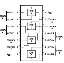
Pinout

  Connection Diagram


Specifications

Symbol
Rating
Value
Unit
VDD*
Supply Voltage : HCC Types
HCF Types
0.5 to + 20
0.5 to + 18
V
V
Vi
Input Voltage
0.5 to VDD + 0.5
V
II
DC Input Current (any one input)
± 10
mA
Ptot
Total Power Dissipation (per package)
Dissipation per Output Transistor
for Top = Full Package-temperature Range
200

100
mW

mW
Top
Operating Temperature : HCC Types
HCF Types
55 to + 125
40 to + 85
°C
°C
Tstg
Storage Temperature
65 to + 150
°C
Stresses above those listed under "Absolute Maximum Ratings" may cause permanent damage to the device. This is a stress
rating only and functional operation of the device at these or any other conditions above those indicated in the operational sections
of this specification is not implied. Exposure to absolute maximum rating conditions for external periods may affect device reliability.
* All voltage values are referred to VSS pin voltage.


Description

In the HCC/HCF4066B series, the HCC4066B (extended temperature range) and HCF4066B (intermediate temperature range) are monolithic integrated circuits, available in 14-lead dual in-line plastic or ceramic package and plastic micropackage. The HCC/HCF4066B is a quad bilateral switch intended for the transmission or multiplexing of analog or digital signals. HCC/HCF4066B is pin-for-pin compatible with HCC/HCF4016B, but exhibits a much lower ON resistance. In addition, the ON resistance is relatively constant over the full input-signal range. The HCC/HCF4066B consists of four independent bilateral switches. A single control signal is required per switch. Both the p and the n device in a given switch are biased ON or OFF simultaneously by the control signal. As shown in schematic diagram, the well of the n-channel device on each switch is either tied to the input when the switch isON or to VSS when the switch is OFF. This configuration eliminates the variation of the switchtransistor threshold voltage with input signal, and thus keeps the ON resistance low over the full operating- signal range. The advantages over singlechannel switches include peak input signal voltage swings equal to the full supply voltage, and more constant ON impedance over the input-signal range. For sample-and-hold applications, however, the HCC/HCF4016B is recommended.


Customers Who Bought This Item Also Bought

Margin,quality,low-cost products with low minimum orders. Secure your online payments with SeekIC Buyer Protection.
Integrated Circuits (ICs)
Computers, Office - Components, Accessories
Static Control, ESD, Clean Room Products
Boxes, Enclosures, Racks
Prototyping Products
DE1
Batteries, Chargers, Holders
View more