GMS81C2112

Features: • 20K/12K bytes ROM(EPROM)• 448 Bytes of On-Chip Data RAM (Including STACK Area)• Minimum Instruction Execution time: - 1uS at 4MHz (2cycle NOP Instruction)• One 8-bit Basic Interval Timer• One 7-bit Watch Dog Timer• Two 8-bit Timer/Counters• 10-...

product image

GMS81C2112 Picture
SeekIC No. : 004354545 Detail

GMS81C2112: Features: • 20K/12K bytes ROM(EPROM)• 448 Bytes of On-Chip Data RAM (Including STACK Area)• Minimum Instruction Execution time: - 1uS at 4MHz (2cycle NOP Instruction)• One 8-...

floor Price/Ceiling Price

Part Number:
GMS81C2112
Supply Ability:
5000

Price Break

  • Qty
  • 1~5000
  • Unit Price
  • Negotiable
  • Processing time
  • 15 Days
Total Cost: $ 0.00

SeekIC Buyer Protection PLUS - newly updated for 2013!

  • Escrow Protection.
  • Guaranteed refunds.
  • Secure payments.
  • Learn more >>

Month Sales

268 Transactions

Rating

evaluate  (4.8 stars)

Upload time: 2024/11/12

Payment Methods

All payment methods are secure and covered by SeekIC Buyer Protection PLUS.

Notice: When you place an order, your payment is made to SeekIC and not to your seller. SeekIC only pays the seller after confirming you have received your order. We will also never share your payment details with your seller.
Product Details

Description


Features:

• 20K/12K bytes ROM(EPROM)
• 448 Bytes of On-Chip Data RAM (Including STACK Area)
• Minimum Instruction Execution time:
  - 1uS at 4MHz (2cycle NOP Instruction)
• One 8-bit Basic Interval Timer
• One 7-bit Watch Dog Timer
• Two 8-bit Timer/Counters
• 10-bit High Speed PWM Output
• One 8-bit Serial Peripheral Interface
• Two External Interrupt Ports
• One Programmable 6-bit Buzzer Driving Port
• 38 I/O Lines
  - 34 Programmable I/O pins (Included 21 high-voltage pins Max. 40V)
  - Three Input Only pins: 1 high-voltage pin
  - One Output Only pin
• Eight Interrupt Sources
  - Two External Sources (INT0, INT1)
  - Two Timer/Counter Sources (Timer0, Timer1)
  - Four Functional Sources (SPI,ADC,WDT,BIT)
• 8-Channel 8-bit On-Chip Analog to Digital Converter
• Oscillator:
  - Crystal
  - Ceramic Resonator
  - External R Oscillator
• Low Power Dissipation Modes
  - STOP mode
  - Wake-up Timer Mode
  - Standby Mode
• Operating Voltage: 2.7V ~ 5.5V (at 4.5MHz)
• Operating Frequency: 1MHz ~ 4.5MHz
• Enhanced EMS Improvement Power Fail Processor (Noise Immunity Circuit)Enhanced EMS Improvement Power Fail Processor (Noise Immunity Circuit)


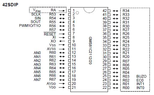
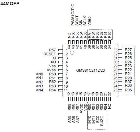
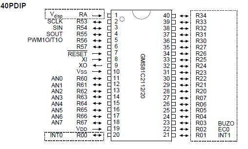
Pinout

  Connection Diagram  Connection Diagram  Connection Diagram


Specifications

Supply voltage ................................................................................................................................................ -0.3 to +7.0 V
Storage Temperature ..................................................................................................................................... -40 to +85 °C
Voltage on Normal voltage pin with respect to Ground (VSS) ......................................................................... -0.3 to VDD+0.3 V
Voltage on High voltage pin with respect to Ground (VSS) ............................................................................. -45V to VDD+0.3 V
Maximum current out of VSSpin ...................................................................................................................... 150 mA
Maximum current into VDDpin ......................................................................................................................... 80 mA
Maximum current sunk by (IOL per I/O Pin) ................................................................................................... 20 mA
Maximum output current sourced by (IOH per I/O Pin) ................................................................................... 8 mA
Maximum current (IOL) ................................................................................................................................ 100 mA
Maximum current (IOH)................................................................................................................................. 50 mA

Note: Stresses above those listed under "Absolute Maximum Ratings" may cause permanent damage to the device. This is a stress rating only and functional operation of the device at any other conditions above those indicated in the operational sections of this specification is not implied. Exposure to absolute maximum rating conditions for extended periods may affect device reliability.


Description

The GMS81C2112 and GMS81C2120 are advanced CMOS 8-bit microcontroller with 12K/20K bytes of ROM. These are a powerful microcontroller which provides a highly flexible and cost effective solution to many VFD applications. GMS81C2112 provides the following standard features: 12K/20K bytes of ROM, 448 bytes of RAM, 8-bit timer/counter, 8-bit A/D converter, 10-bit High Speed PWM Output, Programmable Buzzer Driving Port, 8-bit Basic Interval Timer, 7-bit Watch dog Timer, Serial Peripheral Interface, on-chip oscillator and clock circuitry. They also come with high voltage I/O pins that can directly drive a VFD (Vacuum Fluorescent Display). In addition, the GMS81C2112 and GMS81C2120 support power saving modes to reduce power consumption.


Customers Who Bought This Item Also Bought

Margin,quality,low-cost products with low minimum orders. Secure your online payments with SeekIC Buyer Protection.
Cables, Wires
Optoelectronics
Soldering, Desoldering, Rework Products
Tapes, Adhesives
803
Resistors
View more