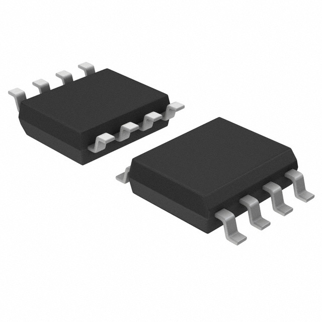
Maximum Collector Emitter Voltage
: 80 V
Isolation Voltage
: 5000 Vrms
Maximum Operating Temperature
: + 110 C
Minimum Operating Temperature
: - 55 C
Packaging
: Tube
Maximum Collector Current
: 50 mA
Input Type
: DC
Maximum Forward Diode Voltage
: 1.4 V
Maximum Power Dissipation
: 200 mW
Package / Case
: PDIP-4
Maximum Collector Emitter Saturation Voltage
: 0.2 V
Current Transfer Ratio
: 600 %
Features: • Current transfer ratio (CTR:MIN.50% at IF =5mA ,VCE =5V)
• High isolation voltage between input and output (Viso=5000 Vrms )
• Compact dual-in-line package EL816:1-channel type
• Pb free
• UL approved (No. E214129)
• VDE approved (No. 132249)
• SEMKO approved (No. 202236/202225)
• NEMKO approved (No. P00102385/P02101854)
• DEMKO approved (No. 310352-05/311822-01)
• FIMKO approved (No. FI 16763 A3)
• CSA approved (No. 1143601)
• BSI approved (No. 8592 / 8593)
• Options available:
- Leads with 0.4"(10.16mm) spacing (M Type)
-Leads bends for surface mounting (S Type)
- Tape and Reel of Type for SMD(Add"-TA" Suffix)
- Tape and Reel of Type for SMD(Add"-TB" Suffix)
- The tape is 16mm and is wound on a 33cm reelApplication• Computer terminals
• System appliances, measuring instruments
• Registers, copiers, automatic vending machines
• Cassette type recorder
• Electric home appliances, such as fan heaters, etc.
• Signal transmission between circuits of different potentials and impedancesSpecifications
| Parameter |
Symbol |
Rating |
Unit |
| Input |
Forward Current |
IF |
50 |
mA |
| Reverse Voltage |
VR |
6 |
V |
| Power Dissipation |
P |
70 |
mW |
| Output |
Collector Power Dissipation |
PC |
150 |
mW |
| Collector Current |
IC |
50 |
mA |
| Collector-Emitter Voltage |
VCEO |
80 |
V |
| Emitter-Collector Voltage |
VECO |
6 |
V |
| Total Power Dissipation |
Ptot |
200 |
mW |
| *1 Isolation Voltage |
Viso |
5000 |
Vrms |
| Operating Temperature |
Topr |
-55~+110 |
°C |
| Storage Temperature |
Tstg |
-55~+125 |
°C |
| *2Soldering Temperature |
Tsol |
260 |
°C |
*1 AC for 1 minute, R.H.= 40 ~ 60% R.H.
-Isolation voltage shall be measured using the following method.
(1) Short between anode and cathode on the primary side and between collector, emitter and base on the secondary side.
(2) The isolation voltage tester with zero-cross circuit shall be used.
(3) The waveform of applied voltage shall be a sine wave
*2 For 10 secondsDescriptionThe EL816 series contains a infrared emitting diode optically coupled to a phototransistor. It is packaged in a 4-pin DIP package and available in wide-lead spacing and SMD option.

 EL816 Data Sheet


