Features: Low On-Resistance: 240
TTL and CMOS Logic Compatible
Low Power: 30 mW
Break-Before-Make Switching
44-V Power Supply Rating
Transition Time: 600 nsPinout
Specifications
Voltage Referenced to V
V+ . . . . . . . . . . . . . . . . . . . . . . . . . . . . . . . . . . . . . . . . . . . . . . . . . . . . . . . . . . . . . . . . . . . . . 44 V
GND . . . . . . . . . . . . . . . . . . . . . . . . . . . . . . . . . . . . . . . . . . . . . . . . . . . . . . . . . . . . . . . . . . . . 25 V
Digital Inputsa, VS, VD . . . . . . . . . . . . . . . . . . . . . . . . . . . . . . . . . . . . . . . . . . . . . . . . . . . . . . (V) 2 V to (V+) +2 V or 20 mA, whichever occurs first
Current (Any Terminal, Except S or D) . . . . . . . . . . . . . . . . . . . . . . . . . . . . . . . . . . . . . . . . . . 30 mA
Continuous Current, S or D . . . . . . . . . . . . . . . . . . . . . . . . . . . . . . . . . . . . . . . . . . . . . . . . . . 20 mA
Peak Current, S or D (Pulsed at 1 ms, 10% Duty Cycle Max) . . . . . . . . . . . . . . . . . . . . . . . . . 40 mA
Storage Temperature (K Suffix) . . . . . . . . . . . . . . . . . . . . . . . . . . . . . . . . . . . . . . . . . . . . . . . 65 to 150
(J and Y Suffix) . . . . . . . . . . . . . . . . . . . . . . . . . . . . . . . . . . . . . . . . . . 65 to 125
Power Dissipation (Package)b
16-Pin CerDIPc . . . . . . . . . . . . . . . . . . . . . . . . . . . . . . . . . . . . . . . . . . . . . . . . . . . . . . . . . . . . 900 mW
LCC-20c . . . . . . . . . . . . . . . . . . . . . . . . . . . . . . . . . . . . . . . . . . . . . . . . . . . . . . . . . . . . . . . . . 900 mW
Notes:
a. Signals on SX, DX or INX exceeding V+ or V will be clamped by internal diodes. Limit forward diode current to maximum current ratings.
b. All leads soldered or welded to PC board.
c. Derate 12 mW/ above 75.
DescriptionThe DG508A_MIL, an 8-channel single-ended analog multiplexer, is designed to connect one of eight inputs to a common output as determined by a 3-bit binary address (A
0, A
1, A
2).
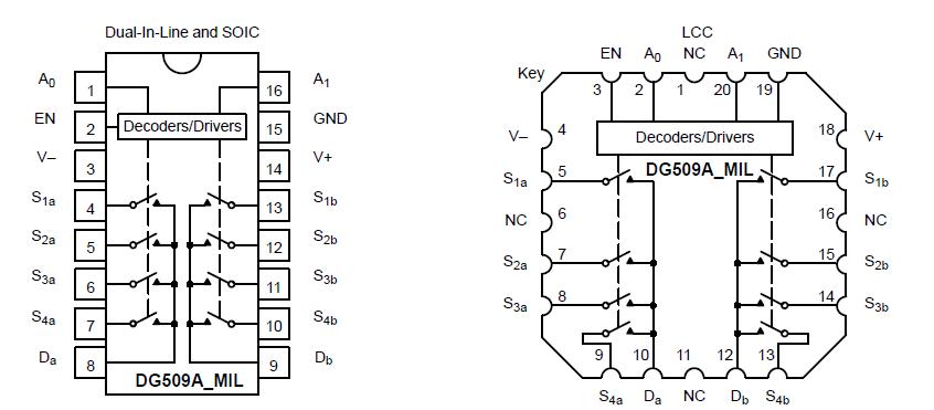
The DG509A_MIL, a dual 4-channel analog multiplexer, is designed to connect one of four differential inputs to a common output as determined by its 2-bit binary address (A
0, A
1) logic. Break-before-make switching action protects against momentary shorting of the input signals.
A channel in the on state conducts current equally well in both directions. In the off state each channel blocks voltages up to the power supply rails, normally 30 V peak-to-peak. An enable (EN) function allows for device selection when several multiplexers are used All control inputs, address (A
X) and enable (EN) are TTL or CMOS compatible over the full specified operating temperature range.
Fabricated in the Vishay Siliconix Plus-40 process, the absolute maximum voltage rating is extended to 44 V, allowing increased operating headroom for standard ±15-V signal swings and operation with ±20-V supplies. An epitaxial layer prevents latch up.
The DG508A_MIL/DG509A_MIL are available in hermetic packages. For plastic packages, use the DG408/409 as pin-for-pin replacements.
For applications requiring address data latching, the DG528/529 is recommended. DG408/409 is recommended for higher precision applications. For wideband/video routing and multiplexing, the DG538A is recommended.

 DG509A_MIL Data Sheet


