CY7C144

Features: • True Dual-Ported memory cells which allow simultaneous reads of the same memory location• 8K x 8 organization (CY7C144)• 8K x 9 organization (CY7C145)• 0.65-micron CMOS for optimum speed/power• High-speed access: 15ns• Low operating power: ICC = 160 ...

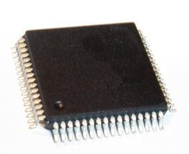
product image

CY7C144 Picture
SeekIC No. : 004320138 Detail

CY7C144: Features: • True Dual-Ported memory cells which allow simultaneous reads of the same memory location• 8K x 8 organization (CY7C144)• 8K x 9 organization (CY7C145)• 0.65-micro...

floor Price/Ceiling Price

Part Number:
CY7C144
Supply Ability:
5000

Price Break

  • Qty
  • 1~5000
  • Unit Price
  • Negotiable
  • Processing time
  • 15 Days
Total Cost: $ 0.00

SeekIC Buyer Protection PLUS - newly updated for 2013!

  • Escrow Protection.
  • Guaranteed refunds.
  • Secure payments.
  • Learn more >>

Month Sales

268 Transactions

Rating

evaluate  (4.8 stars)

Upload time: 2024/12/21

Payment Methods

All payment methods are secure and covered by SeekIC Buyer Protection PLUS.

Notice: When you place an order, your payment is made to SeekIC and not to your seller. SeekIC only pays the seller after confirming you have received your order. We will also never share your payment details with your seller.
Product Details

Description


Features:

• True Dual-Ported memory cells which allow simultaneous reads of the same memory location
• 8K x 8 organization (CY7C144)
• 8K x 9 organization (CY7C145)
• 0.65-micron CMOS for optimum speed/power
• High-speed access: 15ns
• Low operating power: ICC = 160 mA (max.)
• Fully asynchronous operation
• Automatic power-down
• TTL compatible
• Master/Slave select pin allows bus width expansion to 16/18 bits or more
• Busy arbitration scheme provided
• Semaphores included to permit software handshaking between ports
• INT flag for port-to-port communication
• Available in 68-pin PLCC, 64-pin and 80-pin TQFP
• Pin compatible and functionally equivalent to IDT7005/IDT7015


Pinout

  Connection Diagram


Specifications

(Above which the useful life may be impaired. For user guidelines, not tested.)
Storage Temperature ..................................... -65°C to +150°C
Ambient Temperature with
Power Applied.................................................. -55°C to +125°C
Supply Voltage to Ground Potential..................-0.5V to +7.0V
DC Voltage Applied to Outputs
in High Z State.....................................................-0.5V to +7.0V
DC Input Voltage[5]..............................................-0.5V to +7.0V
Output Current into Outputs (LOW) ............................. 20 mA
Static Discharge Voltage .......................................... >2001V
(per MIL-STD-883, Method 3015)
Latch-Up Current.................................................... >200 mA


Description

The CY7C144 and CY7C145 are high-speed CMOS 8K x 8 and 8K x 9 dual-port static RAMs. Various arbitration schemes are included on the CY7C144/5 to handle situations when multiple processors access the same piece of data. Two ports are provided permitting independent, asynchronous access for reads and writes to any location in memory. The CY7C144/5 can be utilized as a standalone 64/72-Kbit dual-port static RAM or multiple devices can be combined in order to function as a 16/18-bit or wider master/slave dual-port static RAM. An M/S pin is provided for implementing 16/18-bit or wider memory applications without the need for separate master and slave devices or additional discrete logic. Application areas include interprocessor/multiprocessor designs, communications status buffering, and dual-port video/graphics memory.

Each port of CY7C144 and CY7C145 has independent control pins: chip enable (CE), read or write enable (R/W), and output enable (OE). Two flags, BUSY and INT, are provided on each port. BUSY signals that the port is trying to access the same location currently being accessed by the other port. The interrupt flag (INT) permits communication between ports or systems by means of a mail box. The semaphores are used to pass a flag, or token, from one port to the other to indicate that a shared resource is in use. The semaphore logic is comprised of eight shared latches. Only one side can control the latch (semaphore) at any time. Control of a semaphore indicates that a shared resource is in use. An automatic power-down feature is controlled independently on each port by a chip enable (CE) pin or SEM pin.


Customers Who Bought This Item Also Bought

Margin,quality,low-cost products with low minimum orders. Secure your online payments with SeekIC Buyer Protection.
RF and RFID
Cable Assemblies
Soldering, Desoldering, Rework Products
Undefined Category
Integrated Circuits (ICs)
Transformers
View more