Features: • 18-Mbit density (2M x 8, 1M x 18, 512K x 36)• 250-MHz clock for high bandwidth• 2-Word burst for reducing address bus frequency• Double Data Rate (DDR) interfaces (data transferred at 500 MHz) @ 250 MHz• Two input clocks (K and K) for precise DDR timing- S...
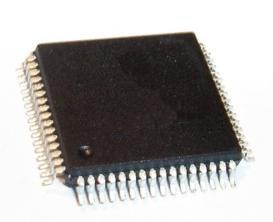
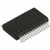
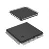
CY7C1392AV18: Features: • 18-Mbit density (2M x 8, 1M x 18, 512K x 36)• 250-MHz clock for high bandwidth• 2-Word burst for reducing address bus frequency• Double Data Rate (DDR) interfaces...
SeekIC Buyer Protection PLUS - newly updated for 2013!
268 Transactions
All payment methods are secure and covered by SeekIC Buyer Protection PLUS.
The CY7C1392AV18/CY7C1393AV18/CY7C1394AV18 are 1.8V Synchronous Pipelined SRAMs equipped with DDR-II SIO (Double Data Rate Separate I/O) architecture. The DDR-II SIO consists of two separate ports to access the memory array. The Read port has dedicated Data outputs and the Write port has dedicated Data inputs to completely eliminate the need to "turn around' the data bus required with common I/O devices. Access to each port is accomplished using a common address bus. Addresses for Read and Write are latched on alternate rising edges of the input (K) clock. Write data is registered on the rising edges of both K and K. Read data is driven on the rising edges of C and C if provided, or on the rising edge of K and K if C/C are not provided. Each address location is associated with two 8-bit words in the case of CY7C1392AV18, two 18-bit words in the case of CY7C1393AV18, and two 36-bit words in the case of CY7C1394AV18, that burst sequentially into or out of the device.
Asynchronous inputs of CY7C1392AV18/CY7C1393AV18/CY7C1394AV18 include impedance match (ZQ). Synchronous data outputs are tightly matched to the two output echo clocks CQ/CQ, eliminating the need for separately capturing data from each individual DDR-II SIO SRAM in the system design. Output data clocks (C/C) enable maximum system clocking and data synchronization flexibility.
All synchronous inputs of CY7C1392AV18/CY7C1393AV18/CY7C1394AV18 pass through input registers controlled by the K/K input clocks. All data outputs pass through output registers controlled by the C/C input clocks (or K/K in single
clock mode). Writes are conducted with on-chip synchronous
self-timed write circuitry.