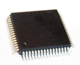
Features: •Separate independent Read and Write data ports-Supports concurrent transactions•167-MHz clock for high bandwidth•2-Word Burst on all accesses•Double Data Rate (DDR) interfaces on both Read and Write ports (data transferred at 333 MHz) @ 167MHz •Two input cl...
CY7C1312AV18: Features: •Separate independent Read and Write data ports-Supports concurrent transactions•167-MHz clock for high bandwidth•2-Word Burst on all accesses•Double Data Rate (DDR...
SeekIC Buyer Protection PLUS - newly updated for 2013!
268 Transactions
All payment methods are secure and covered by SeekIC Buyer Protection PLUS.
Pin Name | I/O | Pin Description |
VREF | Input-Reference | Reference Voltage Input . Static input used to set the reference level for HSTL inputs and Outputs as well as AC measurement points. |
VDD | Power Supply | Power supply inputs to the core of the device |
VSS | Ground | Ground for the device |
VDDQ | Power Supply | Power supply inputs for the outputs of the device |
The CY7C1310AV18/CY7C1312AV18/CY7C1314AV18 are1.8V Synchronous Pipelined SRAMs, equipped with QDR-II architecture. QDR-II architecture consists of two separateports to access the memory array. The Read port hasdedicated Data Outputs of CY7C1310AV18/CY7C1312AV18/CY7C1314AV18 to support Read operations and the Write Port has dedicated Data Inputs to support Write opera-tions. QDR-II architecture has separate data inputs and dataoutputs to completely eliminate the need to "turn-around" thedata bus required with common I/O devices. Access to eachport is accomplished through a common address bus. TheRead address CY7C1310AV18/CY7C1312AV18/CY7C1314AV18 is latched on the rising edge of the K clock andthe Write address is latched on the rising edge of the K clock.
Accesses to the QDR-II Read CY7C1310AV18/CY7C1312AV18/CY7C1314AV18 and Write ports are completelyindependent of one another. In order to maximize datathroughput, both Read and Write ports are equipped with Double Data Rate (DDR) interfaces. Each addresslocation isassociated with two 8-bit words (CY7C1310AV18) or 18-bitwords (CY7C1312AV18) or 36-bit words (CY7C1314AV18)that burst sequentially into or out of the device. Since data canbe transferred into and out of the CY7C1310AV18/CY7C1312AV18/CY7C1314AV18 on every rising edgeof both input clocks (K and K and C and C), memory bandwidth is maximized while simplifying system design by eliminatingbus "turn-arounds."Depth expansion is accomplished with Port Selects for eachport. Port selects allow each port to operate independently.All synchronous inputs of CY7C1310AV18/CY7C1312AV18/CY7C1314AV18 pass through input registers controlledby the K or K input clocks. All data outputs of CY7C1310AV18/CY7C1312AV18/CY7C1314AV18 pass through outputregisters controlled by the C or C (or K or K in a single clockdomain) input clocks. Writes are conducted with on-chip