CS3361

Features: ·Drives Logic Level Power NFET·80V Load Dump·Temperature Compensated Regulation Voltage·Shorted Field Protection Duty Cycle, Self ClearingApplicationThe CS3361 is designed for use in an alternator charging system.In a standard alternator design (Figure 1), the rotor carries the field win...

product image

CS3361 Picture
SeekIC No. : 004316312 Detail

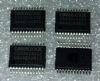
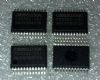
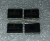
CS3361: Features: ·Drives Logic Level Power NFET·80V Load Dump·Temperature Compensated Regulation Voltage·Shorted Field Protection Duty Cycle, Self ClearingApplicationThe CS3361 is designed for use in an al...

floor Price/Ceiling Price

Part Number:
CS3361
Supply Ability:
5000

Price Break

  • Qty
  • 1~5000
  • Unit Price
  • Negotiable
  • Processing time
  • 15 Days
Total Cost: $ 0.00

SeekIC Buyer Protection PLUS - newly updated for 2013!

  • Escrow Protection.
  • Guaranteed refunds.
  • Secure payments.
  • Learn more >>

Month Sales

268 Transactions

Rating

evaluate  (4.8 stars)

Upload time: 2024/5/22

Payment Methods

All payment methods are secure and covered by SeekIC Buyer Protection PLUS.

Notice: When you place an order, your payment is made to SeekIC and not to your seller. SeekIC only pays the seller after confirming you have received your order. We will also never share your payment details with your seller.
Product Details

Description


Features:

·Drives Logic Level Power NFET
·80V Load Dump
·Temperature Compensated Regulation Voltage
·Shorted Field Protection Duty Cycle, Self Clearing


Application

The CS3361 is designed for use in an alternator charging system.

In a standard alternator design (Figure 1), the rotor carries the field winding. An alternator rotor usually has several N and S poles. The magnetic field for the rotor is produced by forcing current through a field or rotor winding. The Stator windings are formed into a number of coils spaced around a cylindrical core. The number of coils equals the number of pairs of N and S poles on the rotor. The alternating current in the Stator windings is rectified by the diodes and applied to the regulator. By controlling the amount of field current, the magnetic field strength is controlled and hence the output voltage of the alternator.

Referring to Figure 2, a typical application diagram, the oscillator frequency is set by an external capacitor connected between OSC and ground. The sawtooth waveform ramps between 1V and 3V and provides the timing for the system. For the circuit shown the oscillator frequency is approximately 140Hz. The alternator voltage is sensed at Terminal A via the resistor divider network R1/R2 on the Sense pin of the IC. The voltage at the sense pin determines the duty cycle for the regulator. The voltage is adjusted by potentiometer R2. A relatively low voltage on the sense pin causes a long duty cycle that increases the Field current. A high voltage results in a short duty cycle.

The ignition Terminal (I) switches power to the IC through the VCC pin. The Stator pin monitors the voltage from the stator and senses a stopped engine condition. It drives the Lamp pin high after the stator timeout expires. The Lamp pin also goes high when an overvoltage condition is detected on the sense pin. This causes the darlington lamp drive transistor to switch on and pull current through the lamp. If the system voltage continues to increase, the field and lamp output turn off as in an overvoltage or load dump condition.

The SC or Short Circuit pin monitors the field voltage. If the drive output and the SC voltage are simultaneously high for a predetermined period, a short circuit condition is assumed and the output is disabled. The regulator is forced to a minimum short circuit duty cycle.


Specifications

Storage Temperature Range ...............................................................................-55°C to +165°C
Junction Temperature Range ...............................................................................-40°C to +150°C
Continuous Supply.......................................................................................................................27V
ICC Load Dump .....................................................................................................................400 mA
Lead Temperature Soldering Reflow (SMD styles only).......60 sec. max above 183°C, 230°C peak


Description

The CS3361 integral alternator regulator integrated circuit provides the voltage regulation for automotive, 3-phase alternators.

CS3361 drives an external logic level N channel enhancement power FET for control of the alternator field current. In the event of a charge fault, a lamp output pin is provided to drive an external darlington transistor capable of switching on a fault indicator lamp. An overvoltage or no Stator signal condition activates the lamp output.

The CS3361 is available in a 14 lead SO package.


Customers Who Bought This Item Also Bought

Margin,quality,low-cost products with low minimum orders. Secure your online payments with SeekIC Buyer Protection.
Power Supplies - Board Mount
Cables, Wires - Management
Static Control, ESD, Clean Room Products
Tapes, Adhesives
803
Resistors
View more