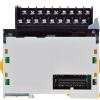
Series: *
Manufacturer: Omron Electronics Inc-IA Div
Accessory Type: -
For Use With/Related Products: -
DescriptionThe CJ1W-ID262 is one member of the CJ1W family which is designed as the SYSMAC CJ-series controller link unit. This device is an FA network that can send and receive large amounts of data easily and at high speed, and also supports data links that enable sharing data between PLCs and computers and a message service that enables sending and receiving data whenever required.
Features of the CJ1W-ID262 are:(1)Large-capacity data links are easily achieved without programming simply by setting data link tables; (2)Up to 20,000(See note 1.) send/receive words can be set per node for Units (up to 62,000 words for Boards); (3)Data links can be performed with up to 4,000(See note 2.) words per node while ensuring data concurrency; (4)User-set data link tables can be changed while data links are operating; (5)Errors for the entire system can be monitored by using error diagnosis support software and a variety of status flags.
The electrical characteristics of the CJ1W-ID262 can be summarized as:(1)Applicable PLC: All CJ-series CPU Units;(2)Number of mountable Units: 8 max.;(3)Installation site: Install onto a CPU Backplane or Expansion Backplane (classified as a CPU Bus Unit);(4)Storage location of network parameters and manually set data link tables: System Bus Unit Area (in the CPU Unit parameter area);(5)Storage location of routing tables: CPU Unit parameter area;(6)Weight: 110 g;(7)Current consumption: 5 V in PLC: 0.35 A.
The usage precautions of CJ1W-ID262 are:(1)Old models and new models can be used mixed on the same network. In that case, however, build the system using the specifications for the old models. The data link send/receive words can be separately set to their maximums when new and old models are mixed; (2)Repeater Units can be used to expand a Wired Controller Link Network. For Wired-to-optical Repeater Units, always use a set of two (1:1) Optical Ring Controller Link Units and Boards cannot be connected to the optical cable section between Repeater Units; (3)Connect Repeater Units so that there are no more than two stages between any two nodes. One set of two Wire-to-Optical Repeater Units is counted as one stage. If you want to know more information such as the electrical characteristics about it, please download the datasheet in www.seekic.com or www.chinaicmart.com.

 CJ1W-ID262 Data Sheet


