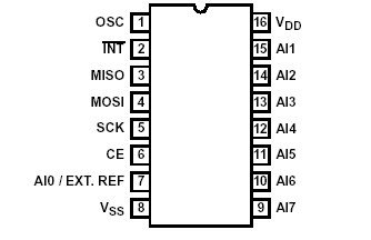
Features: • 10-Bit Resolution• 8-Bit Mode for Single Data Byte Transfers• SPI (Serial Peripheral Interface) Compatible• Operates Ratiometrically Referencing VDD or an External Source• 14s 10-Bit Conversion Time• 8 Multiplexed Analog Input Channels• Indepen...
CDP68HC68A2: Features: • 10-Bit Resolution• 8-Bit Mode for Single Data Byte Transfers• SPI (Serial Peripheral Interface) Compatible• Operates Ratiometrically Referencing VDD or an Externa...
SeekIC Buyer Protection PLUS - newly updated for 2013!
268 Transactions
All payment methods are secure and covered by SeekIC Buyer Protection PLUS.
DescriptionThe CDP6805E3E is a plug-and-play drop-in replacement for the original IC. MILESTM ca...
The CDP68HC68A2 is a CMOS 8-bit or 10-bit successive approximation analog to digital converter (A/D) with a standard Serial Peripheral Interface (SPI) bus and eight multiplexed analog inputs. Voltage referencing is user selectable to be relative to either VDD or analog channel 0 (AI0). The analog inputs can range between VSS and VDD.
The CDP68HC68A2 employs a switched capacitor, successive approximation A/D conversion technique which provides an inherent sample-and-hold function. An onchip Schmitt oscillator provides the internal timing for the A/D converter. The Schmitt input can be externally clocked or connected to a single, external capacitor to form an RC oscillator with a period of approximately 10-30ns per picofarad.
Conversion times are proportional to the oscillator period. At CDP68HC68A2 maximum specified frequency of 1MHz, 10-bit conversions take 14ms per channel. At the same frequency, 8-bit conversions consume 12ms per channel.
The versatile modes of the CDP68HC68A2 allow any combination of the eight input channels to be enabled and any one of the selected channels to be specified as the "starting" channel. Conversions proceed sequentially beginning with the starting channel. Nonselected channels are skipped. CDP68HC68A2 can be selected to: sequence from channel to channel on command; sequence through channels automatically, converting each channel one time; or sequence repeatedly through all channels.
The results of 10-bit conversions are stored in 8-bit register pairs (one pair per channel). The two most significant bits CDP68HC68A2 are stored in the first register of each pair and the eight least significant bits are stored in the second register of the pair. To allow faster access, in the 8-bit mode, the results of conversions are stored in a single register per channel.
A read-only STATUS register facilitates monitoring the status of conversions. The STATUS register CDP68HC68A2 can simply be polled or the INT pin can be enabled for interrupt driven communications.