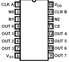
Features: • Provides Direct Control of Up to 7 Input and 7 Output Devices• CHIP ENABLE (CE) Allows Easy Expansion for Multilevel I/O SystemsPinoutSpecificationsDC Supply Voltage Range, (VDD) (All voltage values referenced to VSS terminal) CDP1853 . . . . . . . . . . . . . . . . . . . ....
CDP1853C: Features: • Provides Direct Control of Up to 7 Input and 7 Output Devices• CHIP ENABLE (CE) Allows Easy Expansion for Multilevel I/O SystemsPinoutSpecificationsDC Supply Voltage Range, (...
SeekIC Buyer Protection PLUS - newly updated for 2013!
268 Transactions
All payment methods are secure and covered by SeekIC Buyer Protection PLUS.
The CDP1853 and CDP1853C are 1 of 8 decoders designed for use in general purpose microprocessor systems. These devices, which are functionally identical, are specifically designed for use as gated N-bit decoders and interface directly with the 1800-series microprocessors without additional components. The CDP1853 has a recommended operating voltage range of 4V to 10.5V, and the CDP1853C has a recommended operating voltage range of 4V to 6.5V.
When CHIP ENABLE (CE) CDP1853C is high, the selected output will be true (high) from the trailing edge of CLOCK A (high-to-low transition) to the trailing edge of CLOCK B (high-to-low transition). All outputs will be low when the device is not selected (CE = 0) and during conditions of CLOCK A and CLOCK B as shown in Figure 2. The CDP1853 inputs N0, N1, N2, CLOCK A, and CLOCK B are connected to an 1800-series microprocessor outputs N0, N1, N2, TPA, and TPB respectively, when used to decode I/O commands as shown in Figure 5. The CHIP ENABLE (CE) input provides the capability for multiple levels of decoding as shown in Figure 6.
The CDP1853 can also be used as a general 1 of 8 decoder for I/O and memory system applications as shown in Figure 4.
The CDP1853 and CDP1853C are supplied in hermetic 16-lead dual-in-line ceramic (D suffix) and plastic (E suffix) packages.