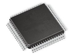
Features: The C8051F330/1/2/3/4/5 SoC family includes several key enhancements to the CIP-51 core and periph- erals to improve performance and ease of use in end applications.
The extended interrupt handler provides 14 interrupt sources into the CIP-51 (as opposed to 7 for the stan-dard 8051), allowing numerous analog and digital peripherals to interrupt the controller. An interrupt driven system requires less intervention by the MCU, giving it more effective throughput. The extra interrupt sources are very useful when building multi-tasking, real-time systems.
Eight reset sources are available: power-on reset circuitry (POR), an on-chip VDD monitor (forces reset when power supply voltage drops below VRST as given in Table 10.1 on page 104), a Watchdog Timer, a Missing Clock Detector, a voltage level detection from Comparator0, a forced software reset, an external reset pin, and an illegal Flash access protection circuit. Each reset source except for the POR, Reset Input Pin, or Flash error may be disabled by the user in software. The WDT may be permanently enabled in soft-ware after a power-on reset during MCU initialization.
The internal oscillator factory calibrated to 24.5 MHz ±2%. This internal oscillator period may be user pro-grammed in ~0.5% increments. An additional low-frequency oscillator is also available which facilitates low-power operation. An external oscillator drive circuit is included, allowing an external crystal, ceramic resonator, capacitor, RC, or CMOS clock source to generate the system clock. If desired, the system clock source may be switched on-the-fly between both internal and external oscillator circuits. An external oscil-lator can also be extremely useful in low power applications, allowing the MCU to run from a slow (power saving) source, while periodically switching to the fast (up to 25 MHz) internal oscillator as needed.
Pinout
 Specifications
| Parameter |
Conditions |
Min |
Typ |
Max |
Units |
| Ambient temperature under bias |
|
55 |
- |
125 |
°C |
| Storage Temperature |
|
65 |
- |
150 |
°C |
Voltage on any Port I/O Pin or RST with
respect to GND |
|
0.3 |
- |
5.8 |
V |
Voltage on VDD with respect to GND
|
|
0.3 |
- |
4.2 |
V |
Maximum Total current through VDD or GND
|
|
- |
- |
500 |
mA |
Maximum output current sunk by RST or any
Port pin |
|
- |
- |
100 |
mA |
Note: Stresses above those listed under "Absolute Maximum Ratings" may cause permanent damage to the device.
This is a stress rating only and functional operation of the devices at those or any other conditions above
those indicated in the operation listings of this specification is not implied. Exposure to maximum rating
conditions for extended periods may affect device reliability. |

 C8051F335 Data Sheet


