Series: -
Transistor Type: -
Current - Collector (Ic) (Max): -
FET Feature: Logic Level Gate
Voltage - Collector Emitter Breakdown (Max): -
Vce Saturation (Max) @ Ib, Ic: -
Current - Collector Cutoff (Max): -
DC Current Gain (hFE) (Min) @ Ic, Vce: -
Vgs(th) (Max) @ Id: 3V @ 250µA
Frequency - Transition: -
Mounting Type: Surface Mount
Packaging: Cut Tape (CT)Alternate Packaging
FET Type: MOSFET P-Channel, Metal Oxide
Drain to Source Voltage (Vdss): 40V
Power - Max: 2.5W
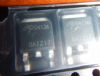
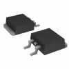
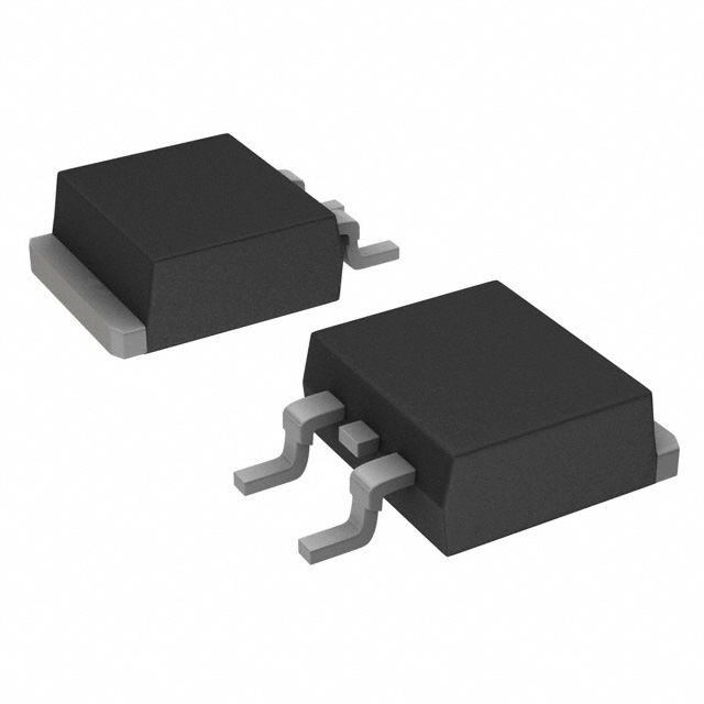
Package / Case: TO-252-3, DPak (2 Leads + Tab), SC-63
Current - Continuous Drain (Id) @ 25° C: 40A
Gate Charge (Qg) @ Vgs: 41nC @ 10V
Supplier Device Package: TO-252
Manufacturer: Alpha & Omega Semiconductor Inc
Rds On (Max) @ Id, Vgs: 22 mOhm @ 12A, 10V
Input Capacitance (Ciss) @ Vds: 1870pF @ 20V
Features: VDS (V) = -40V
ID = -40A (VGS = -10V)
RDS(ON) < 22m� (VGS = -10V)
RDS(ON) < 29m� (VGS = -4.5V)Specifications
| Parameter |
Symbol |
Maximum |
Units |
| Drain-Source Voltage |
VDS |
-40 |
V |
| Gate-Source Voltage |
VGS |
±20 |
V |
| Continuous Drain Current B,H |
TC=25 |
ID |
-40 |
A |
| TC=100 |
-28 |
A |
| Pulsed Drain Current C |
IDM |
-50 |
A |
| Power Dissipation B |
TC=25 |
PD |
62.5 |
W |
| TC=100 |
31 |
W |
| Power Dissipation A |
TA=25 |
PDSM |
2.5 |
W |
| TA=70 |
1.6 |
| Avalanche Current C |
IAR |
-35 |
A |
| Repetitive avalanche energy L=0.1mH C |
EAR |
61 |
mJ |
| Junction and Storage Temperature Range |
TJ, TSTG |
-55 to 175 |
|
A: The value of RJJA is measured with the device in a still air environment with T A =25°C. The power dissipation PDSM and current rating IDSM are
based on TJMAX)=150°C, using steady state junction-to-ambient thermal resistance.
B. The power dissipation PD is based on TJ(MAX)=175°C, using junction-to-case thermal resistance, and is more useful in setting the upper
dissipation limit for cases where additional heatsinking is used.
C: Repetitive rating, pulse width limited by junction temperature T J(MAX)=175°C.
D. The RJJA is the sum of the thermal impedence from junction to case R JJC and case to ambient.
E. The static characteristics in Figures 1 to 6 are obtained using t 300 s pulses, duty cycle 0.5% max.
F. These curves are based on the junction-to-case thermal impedence which is measured with the device mounted to a large heatsink, assuming
a maximum junction temperature of TJ(MAX)=175°C. The SOA curve provides a single pulse rating.
G. These tests are performed with the device mounted on 1 in 2 FR-4 board with 2oz. Copper, in a still air environment with T A=25°C.
H. The maximum current rating is limited by bond-wires.
*This device is guaranteed green after data code 8X11 (Sep 1 ST 2008).
Rev1: Oct 2008
DescriptionThe AOD4189 uses advanced trench technology and design to provide excellent RDS(ON) with low gate charge. With the excellent thermal resistance of the DPAK package, this device is well suited for high current load applications.
-RoHS Compliant
-Halogen Free*
 AOD4189 Data Sheet