Features: Several configuration options can be configured by hardware. The Mobile Intel Pentium 4 Processor-M samples its hardware configuration at reset, on the active-to-inactive transition of RESET#. For specifications on these options, please refer to Table 40.The sampled information configure...
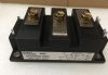
ADSTB1: Features: Several configuration options can be configured by hardware. The Mobile Intel Pentium 4 Processor-M samples its hardware configuration at reset, on the active-to-inactive transition of RES...
SeekIC Buyer Protection PLUS - newly updated for 2013!
268 Transactions
All payment methods are secure and covered by SeekIC Buyer Protection PLUS.
Several configuration options can be configured by hardware. The Mobile Intel Pentium 4 Processor-M samples its hardware configuration at reset, on the active-to-inactive transition of RESET#. For specifications on these options, please refer to Table 40.
The sampled information configures the processor for subsequent operation. These configuration options cannot be changed except by another reset. All resets reconfigure the processor.
The use of AutoHALT, Stop-Grant, Sleep, Deep Sleep and Deeper Sleep states is allowed in Mobile Intel Pentium 4 Processor-M based systems to reduce power consumption by stopping the clock to internal sections of the processor, depending on each particular state. See Figure 35 for a visual representation of the processor low-power states.
AutoHALT is a low-power state entered when the processor executes the HALT instruction. The processor will transition to the Normal state upon the occurrence of SMI#, BINIT#, INIT#,LINT[1:0] (NMI, INTR), or PSB interrupt message. RESET# will cause the processor to immediately initialize itself.
The return from a System Management Interrupt (SMI) handler can be to either Normal Mode or the AutoHALT Powerdown state. See the Intel Architecture Software Developer's Manual,Volume III: System Programmer's Guide for more information.
Symbol |
Parameter |
Min |
Max |
Unit |
TSTORAGE | Processor storage temperature2 |
-40 |
85 |
°C |
VCC | Any processor supply voltage with respect to VSS1 |
-0.3 |
1.75 |
V |
VinAGTL+ | AGTL+ buffer DC input voltage with respect to VSS |
-0.1 |
1.75 |
V |
VinAsynch_GTL+ | Asynch GTL+ buffer DC input voltage with respect to VSS |
-0.1 |
1.75 |
V |
IVID | Max VID pin current |
5 |
mA |