Features: Four Delay Lines with the Ability to IndependentlyAdjust All EdgesPin Compatible and Functionally Equivalent with theBT624Reduced Power Dissipation44-Lead PLCC Package with Internal Heat Spreader
Pinout Specifications
| Parameter |
Symbol |
Min Max |
Units |
VEE (Relative to GND)
Voltage on Any Digital Pin
Output Current
Ambient Operating Temperature
Storage Temperature
Junction Temperature
Soldering Temperature2
(Soldering, 5 sec)
|
TA
TS
TJ
TSOL
|
6.0
VEE
55
65 |
0
50
+70
+150
+150
+260
|
V
V
mA
°C
°C
°C
°C
|
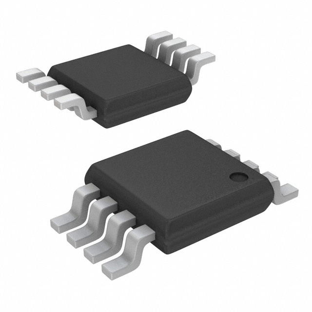
DescriptionThe AD53020 is a four-channel delay line designed for use inautomatic test equipment and digital logic systems. High speedbipolar transistors and a 44-lead plastic PLCC package withinternal heat spreader provide high frequency performance at aminimum of space, cost and power dissipation.
Featuring full pin compatibility and functional equivalence tothe BT624, the AD53020 offers independent analog control ofpositive and negative edges with five delay ranges. The AD53020offers attractive performance with optimized power dissipationand linear delay vs. program voltage control. This device is alsovery stable over operating conditions and has very low jitter.
Digital inputs of AD53020 are ECL compatible. They can either be providedindependently for each channel (IN1, IN1 through IN4,IN4), or fanned out to all channels from Channel 2 (IN2,IN2). The choice of these two options is made by setting theDRVMODE input, with ECL Logic 0 providing four independentchannels, and ECL Logic 1 enabling a logical OR functionbetween each channel and the Channel Number 2.
For maximum timing accuracy, differential signals are recommendedfor use with the digital inputs. However, single-endedoperation is also supported and it is facilitated through the useof the VBB midpoint level generated on-chip. To make use ofthis feature,connect the VBB output to the inverting input ofeach channel. It is also advisable, when using the VBB output,to decouple this signal with a 0.1 mF ceramic capacitor to ground.The outputs of the AD53020 are ECL compatible and shouldbe terminated by 50 W to 2.0 V at the inputs of the gatesthey drive.

 AD53020 Data Sheet