Features: Class D/1-Bit Audio Power Output Stage
5 V Analog and Digital Supply Voltages
Power Stage Power Supply 8 V to 20 V
Output Power @ 0.1% THD + N
Stereo Mode
2 * 20 W @ 4 @ 14.4 V
2 * 20 W @ 8 @ 20 V
Mono Mode
1 * 40 W @ 4 @ 20 V
RON < 320 m (per Transistor)
Efficiency > 85% @ Full Power/8
Clickless Mute Function
Turn-On and Turn-Off Pop Suppression
Short-Circuit Protection
Overtemperature Protection
Data Loss Protection
2-Channel BTL Outputs or
4-Channel Single-Ended Outputs
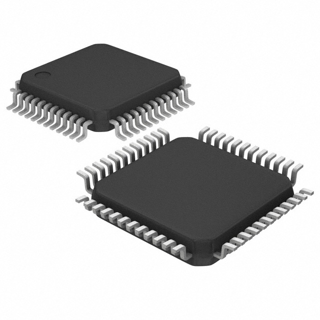
52-Lead Exposed Pad TQFP Package
Low Cost DMOS Process ApplicationPC Audio Systems
Minicomponents
Automotive Amplifiers
Home Theater Systems
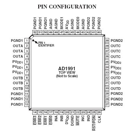
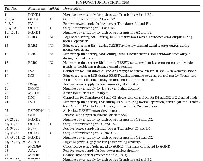
TelevisionsPinout
 SpecificationsAVDD, DVDD to AGND, DGND . . . . . . . . . . . . . 0.3 V to +6.5 V
PVDDX to PGNDx2 . . . . . . . . . . . .. . . . . . . . 0.3 V to +30.0 V
AGND to DGND to PGNDx . . . . . . . . .. . . . . . . 0.3 V to +0.3 V
AVDD to DVDD . . . . . . . . . . . . . . . . . . . . . . . . 0.5 V to +0.5 V
Operating Temperature Range (Ambient)
Industrial . . . . . . . . . . . . . . . . . . . . . . . . 40°C to +85°C
Storage Temperature Range . . . . . . .. . . . 65°C to +150°C
Maximum Junction Temperature . . . . . . . . . . . . . . . . . . 150°C
JC Thermal Resistance3 . . . . . . . . . . . . .. . . . . . . . . . . 1°C/W
Lead Temperature
Soldering (10 sec) . . . . . . . . . . . . . . . . . . . . . . . . . . . 260°C
Vapor Phase (60 sec) . . . . . . . . . . . . . . . . . . . . . . . . 215°C
Infrared (15 sec) . . . . . . . . . . . . . . . . . . . . . . . . . . . . 220°C
DescriptionThe AD1991 is a 2-channel BTL or 4-channel single-ended class D audio power output stage. The part is configured during reset to be in either 2-channel mode or 4-channel mode.
To protect the IC as well as the connected speakers, the AD1991 provides turn-on and turn-off pop suppression, short-circuit protection, and overtemperature shutdown. To control the IC, a power-down/reset input and a mute pin are available.
The output stage can be operated over a power supply range from 8 V to 20 V.
In 2-channel mode, Transistors A1, B2, C1, and D2 are turned on by a Logic 1 on inputs INA and INC, and Transistors A2,B1, C2, and D1 are turned on by a Logic 0 on inputs INA and INC. In 4-channel mode, Transistors A1, B1, C1, and D1 are turned on by a Logic 1 on the four inputs, and Transistors A2,B2, C2, and D2 are turned on by a Logic 0 on the four inputs (see the Functional Block Diagrams).

 AD1991 Data Sheet


