Pinout Description
The AC104-QF has the following features including (1)Baseline Wander Compensation;(2)Multi-Function LED outputs;(3)Reverse polarity detection and correction with Register Bit indication Automatic or Forced;(4)8 programmable interrupts.
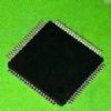
The AC104-QF is a highly integrated, 3.3V, low power, four port, 10Base-T/100Base-TX/FX, Ethernet transceiver implemented in 0.35mm CMOS technology. AC104-QF's Multiple modes of operation including normal operation, test mode and power saving mode are available through either hardware or software control.Features include MAC interfaces, ENDECs,Scrambler/Descrambler, and Auto-Negotiation(ANeg) with support for parallel detection. The transmitter includes a dual-speed clock synthesizer that only needs one external clock source. The chip AC104-QF has built-in wave shaping driver circuit for both 10Mbps and 100Mbps, eliminating the need for an external hybrid filter. The receiver has an adaptive equalizer / DC restoration circuit for accurate clock /data recovery for the 100Base-TX signal. It also provides an on-chip low pass filer / Squelch circuit for the 10Base-T signal.Many of the pins of these devices have multiple functions. The multi-function pins will be designated by bolding of the pin number. Separate descriptions of these pins will be listed in the proper sections. Designers must assure that they have identified all modes of operation prior to final design.
The INTR pin on the Phy of AC104-QF will be asserted whenever one of 8 selectable interrupt events occur. Assertion state is programmable to either high or low through the INTR_LEVL register bit. Selection is made by setting the appropriate bit in the upper half of the Interrupt Control / Status register. When the INTR bit goes active, the MAC interface is required to read the Interrupt Control / Status register to determine which event caused the interrupt. The Status bits are read only and clear on read. When INTR is not asserted, the pin is held in a high impedance state.When configured to run in 100Base-TX mode, either through hardware configuration, software configuration or ANeg, the Phy will support all the features and parameters of the industry standards.

 AC104-QF Data Sheet


