Features: ▪ 5 to 17 V operation▪ Wide output current range (10 to 150 mA per output)▪ 3 × 7 bit Dot Correction current settings▪ 31 bit shift register▪ 3 ×10 bit PWM luminance settings▪ Buffered output control pins▪ Up to 5 MHz serial / PWM clock frequency...
A6280: Features: ▪ 5 to 17 V operation▪ Wide output current range (10 to 150 mA per output)▪ 3 × 7 bit Dot Correction current settings▪ 31 bit shift register▪ 3 ×10 bit PWM lu...
SeekIC Buyer Protection PLUS - newly updated for 2013!
268 Transactions
All payment methods are secure and covered by SeekIC Buyer Protection PLUS.
Characteristic | Symbol | Notes | Rating | Units |
Supply Voltage | VIN | 17 | V | |
Output Voltage | VO | 0.5 to 17 | V | |
Output Current | IO | 170 | mA | |
Ground Current | IGND | 600 | mA | |
Logic Input Voltage Range | VI | 0.3 to 7 | V | |
Operating Ambient Temperature | TA | Range E | 40 to 85 | °C |
Maximum Junction Temperature | TJ(max) | 150 | °C | |
Storage Temperature | Tstg | 40 to 150 | °C |
The A6280 is a 3 bit constant current LED driver that has a wide range of output currents. The A6280 controls LED luminance with a pulse width modulation (PWM) scheme that gives the application the capability of displaying a billion colors. The overall maximum current is set by an external resistor.
The LED luminance is controlled by performing PWM control on the outputs. The luminance data of the PWM signal for each LED is stored in three 10 bit registers. Each LED can be dot corrected by a 7 bit scalar register that scales the maximum current from 100% down to 36.5%. All the internal latched registers are loaded by a 31 bit serial shift register. One bit is used to control the type of data loaded into the registers, either dot correction / clock divider ratio or luminance data. The remaining 30 bits are used for the data. This helps reduce the pin count of the A6280. To further lower the A6280 pin count, the PWM clock and the serial bus clock share the same pin and work concurrently to control LED luminance and to load data.
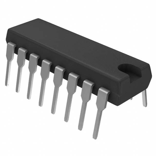
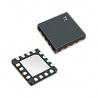
The A6280 is designed to minimize the number of components needed to drive LEDs with large pixel spacing. Several A6280s can be daisy chained together and controlled by just four control signals (Clock, Serial Data, Latch, and Output Enable). Each of these inputs has buffered outputs on chip. Also, the VIN pin can be tied to the LED voltage supply bus, thus eliminating the need for a separate chip supply bus or an external linear regulator. The A6280 is supplied in a 16 pin dual in line (DIP) package (suffix 'A') package and in a 16 lead QFN/MLP (suffix 'ES') package.
The packages are lead (Pb) free with 100% matte-tin leadframe plating.