Features: Low RDS(ON)outputs
Automatic current decay mode detection/selection
Mixed and Slow current decay modes
Synchronous rectification for low power dissipation
Internal UVLO and thermal shutdown circuitry
Crossover-current protectionPinout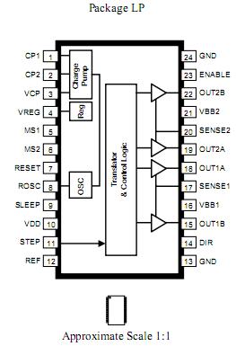 Specifications
Load Supply Voltage,VBB...................................35 V
Output Current, IOUT.......................................±2 A
Logic Input Voltage, VIN ....................0.3 V to 7 V
Sense Voltage, VSENSE .................................. 0.5 V
Reference Voltage, VREF ..... ........................4 V
Operating Temperature Range
Ambient, TA ................................. 20°C to 85°C
Junction Temperature, TJ(MAX)..................... 150°C
Storage Temperature, T ..............55°C to 150°C
DescriptionThe A3983 is a complete microstepping motor driver with built-in translator for easy operation. It is designed to operate bipolar stepper motors in full-, half-, quarter-, and eighth-step modes, with an output drive capacity of up to 35V and ±2A. The A3983 includes a fixed off-time current regulator which has the ability to operate in Slow or Mixed decay modes.
The translator is the key to the easy implementation of the A3983. Simply inputting one pulse on the STEP input drives the motor one microstep. There are no phase sequence tables, high frequency control lines, or complex interfaces to program. The A3983 interface is an ideal fit for applications where a complex microprocessor is unavailable or is overburdened.
The chopping control in the A3983 automatically selects the current decay mode (Slow or Mixed). When a signal occurs at the STEP input pin, the A3983 determines if that step results in a higher or lower current in each of the motor phases. If the change is to a higher current, then the decay mode is set to Slow decay. If the change is to a lower current, then the current decay is set to Mixed (set initially to a fast decay for a period amounting to 31.25% of the fixed off-time, then to a slow decay for the remainder of the off-time). This current decay control scheme results in reduced audible motor noise, increased step accuracy, and reduced power dissipation.
Internal synchronous rectification control circuitry is provided to improve power dissipation during PWM operation. Internal circuit protection includes: thermal shutdown with hysteresis, undervoltage lockout (UVLO), and crossover-current protection. Special poweron sequencing is not required.
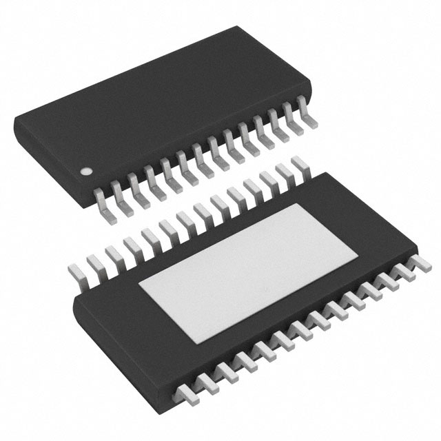
The A3983 is supplied in a low-profile (1.2mm maximum height), 24-pin TSSOP with exposed thermal pad (suffix LP). It is lead (Pb) free, with 100% matte tin leadframe plating.

 A3983 Data Sheet