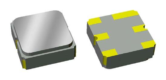
Features: • For GSM applications, IF stage• Usable bandwidth 166 KHz• Low loss• Low group delay variation• Single-ended or balanced operation• Ceramic Surface Mount Package (SMP)• Small sizeSpecifications Parameter (3) Minimum Typical Maximum Unit...
855874: Features: • For GSM applications, IF stage• Usable bandwidth 166 KHz• Low loss• Low group delay variation• Single-ended or balanced operation• Ceramic Surface Mou...
SeekIC Buyer Protection PLUS - newly updated for 2013!
268 Transactions
All payment methods are secure and covered by SeekIC Buyer Protection PLUS.
Parameter (3) | Minimum | Typical | Maximum | Unit |
Center Frequency, fo | - | 400 | - | MHz |
Insertion Loss at 400 MHz Excluding losses due to matching Including losses in matching test circuit shown below |
- | 2.6 4.4 |
4.2 6.0 |
dB dB |
Lower 2 dB Bandedge | - | 399.8 | 4.2 6.0 |
MHz |
Upper 2 dB Bandedge | 400.083 | 400.2 | - | MHz |
9 dB Bandwidth | - | 0.55 |
0.8 |
MHz |
12 dB Bandwidth | - | 0.58 | 1.2 | MHz |
22 dB Bandwidth | - | 0.69 | 1.6 | MHz |
Amplitude Variation 399.917 - 400.083 MHz |
- | 0.21 | 2 | dB |
Group Delay Variation 399.917 - 400.083 MHz |
- | 300 | 1000 | nsec |
Rejection (4) 398.5 - 399.2 MHz 399.2 - 399.4 MHz 399.4 - 399.6 MHz 400.4 - 400.6 MHz 400.6 - 400.8 MHz 400.8 - 401.5 MHz |
22 12 9 9 12 22 |
37 34 28 26 34 37 |
- - - - - - |
dB dB dB dB dB dB |
Out of Band Rejection 50 - 398.5 MHz 401.5 - 500 MHz |
37 37 |
45 45 |
- - |
dB dB |
Optimal Source Impedance (5) | - | 560||44nH | - | |
Optimal Impedance (5) | - | 860||34nH | - |
Notes:
1. All specifications are based on the test circuit shown below
2. In production, devices will be tested at room temperature to a guardbanded specification to ensure electrical ompliance over temperature
3. Electrical margin has been built into the design to account for the variations due to temperature drift and anufacturing tolerances
4. Relative to insertion loss at 400 MHz
5. This is the complex conjugate of the unmatched filter's impedance resulting in maximum power transfer