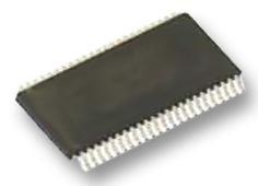
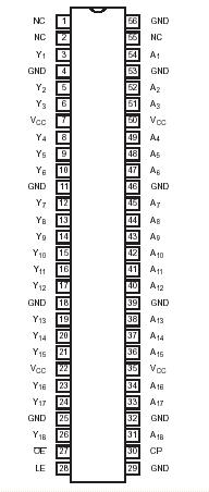
Features: • Wide supply voltage range of 2.3 V to 3.6 V• Complies with JEDEC standard no. 8-1A.• CMOS low power consumption• Direct interface with TTL levels• Current drive ± 24 mA at 3.0 V• MULTIBYTETM flow-through standard pin-out architecture• Low induc...
74ALVCHT16835: Features: • Wide supply voltage range of 2.3 V to 3.6 V• Complies with JEDEC standard no. 8-1A.• CMOS low power consumption• Direct interface with TTL levels• Current d...
SeekIC Buyer Protection PLUS - newly updated for 2013!
268 Transactions
All payment methods are secure and covered by SeekIC Buyer Protection PLUS.
US $2 - 2.02 / Piece
Buffers & Line Drivers 16-Bit Buffer/Driver With 3-State Outputs
SYMBOL |
PARAMETER | CONDITIONS |
RATING |
UNIT |
VCC |
DC supply voltage |
0.5 to +4.6 |
V | |
IIK |
DC input diode current | VI<0 |
-50 |
mA |
VI |
DC input voltage | For control pins1 |
0.5 to +4.6 |
V |
For data inputs1 |
0.5 to VCC +0.5 | |||
IOK |
DC output diode current | VO>VCC or VO<0 |
±50 |
mA |
VO |
DC output voltage | Note 1 |
-50toVcc+0.5 |
V |
IO |
DC output source or sink current | VO = 0 to VCC |
±50 |
mA |
IGND, ICC |
DC VCC or GND current |
±100 |
mA | |
Tstg |
Storage temperature range |
-65to+150 |
||
PTOT |
Power dissipation per package plastic thin-medium-shrink (TSSOP) |
For temperature range: 40 to +125 °C above +55°C derate linearly with 8 mW/K |
600 |
m/W |
JA |
Package thermal impedance | See Note 2 |
93 |
/W |
The 74ALVCHT16835 is a 18-bit registered driver. Data flow is controlled by active low output enable (OE), active high latch enable (LE) and clock inputs (CP).
When LE is HIGH, the A to Y data flow is transparent. When LE is LOW and CP is held at LOW or HIGH, the data is latched; on the LOW to HIGH transient of CP the A-data is stored in the latch/flip-flop.
WhenOE of the 74ALVCHT16835 is LOW the outputs are active. When OE is HIGH, the outputs go to the high impedance OFF-state. Operation of the OE input does not affect the state of the latch/flip-flop.
To ensure the high-impedance state of the 74ALVCHT16835 during power up or power down, OE should be tied to VCC through a pullup resistor; the minimum value of the resistor is determined by the current-sinking