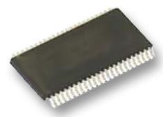
Features: • Wide supply voltage range of 1.2V to 3.6V• Complies with JEDEC standard no. 8-1A.• CMOS low power consumption• Direct interface with TTL levels• Current drive ± 24 mA at 3.0 V• MultibyteEflow-through standard pin-out architecture• Low inductanc...
74ALVCH16823: Features: • Wide supply voltage range of 1.2V to 3.6V• Complies with JEDEC standard no. 8-1A.• CMOS low power consumption• Direct interface with TTL levels• Current dri...
SeekIC Buyer Protection PLUS - newly updated for 2013!
268 Transactions
All payment methods are secure and covered by SeekIC Buyer Protection PLUS.
US $2 - 2.02 / Piece
Buffers & Line Drivers 16-Bit Buffer/Driver With 3-State Outputs
SYMBOL |
PARAMETER | CONDITIONS |
RATING |
UNIT |
VCC |
DC supply voltage |
0.5 to +4.6 |
V | |
IIK |
DC input diode current | VI<0 |
-50 |
mA |
VI |
DC input voltage | For control pins1 |
0.5 to +4.6 |
V |
For data inputs1 |
0.5 to VCC +0.5 | |||
IOK |
DC output diode current | VO>VCC or VO<0 |
±50 |
mA |
VO |
DC output voltage | Note 1 |
-50toVcc+0.5 |
V |
IO |
DC output source or sink current | VO = 0 to VCC |
±50 |
mA |
IGND, ICC |
DC VCC or GND current |
±100 |
mA | |
Tstg |
Storage temperature range |
-65to+150 |
||
PTOT |
Power dissipation per package plastic medium-shrink (SSOP) plastic thin-medium-shrink (TSSOP) |
For temperature range: 40 to +125 °C above +55°C derate linearly with 11.3 mW/ above +55°C derate linearly with 8 mW/K |
850 600 |
m/W |
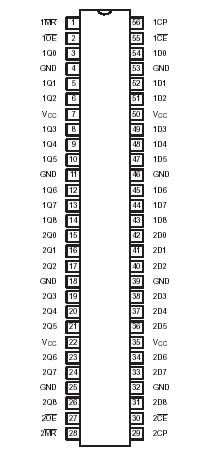
The 74ALVCH16823 is a 18-bit edge-triggered flip-flop featuring separate D-type inputs for each flip-flop and 3-state outputs for bus oriented applications. Incorporates bushold data inputs which eliminate the need for external pull-up resistors to hold unused inputs. The74ALVCH16823 consists of two sections of nine edge-triggered flip-flops. A clock (CP) input, an output-enable (OE) input, a Master reset (MR) input and a clock-enable( CE) input are provided for each total 9-bit section.
With the clock-enable (CE) input LOW, the D-type flip-flops of the 74ALVCH16823will store the state of their individual D-inputs that meet the set-up and hold time requirements on the LOW-to-HIGH CP transition. Taking CE HIGH disables the clock buffer, thus latching the outputs. Taking the Master reset (MR) input LOW causes all the Q outputs to go LOW dependently of the clock.
When OE is LOW, the contents of the flip-flops are available at the outputs. When the OE is HIGH, the outputs go to the high impedance OFF-state. Operation of the OE input does not affect the state of flip-flops.
Active bus hold circuitry of the 74ALVCH16823 is provided to hold unused or floating data inputs at a valid logic level.