Features: • Wide supply voltage range of 1.2 V to 3.6 V• Complies with JEDEC standard no. 8-1A.• CMOS low power consumption• Direct interface with TTL levels• Current drive ± 12 mA at 3.0 V• MULTIBYTETM flow-through standard pin-out architecture• Low induc...
74ALVC162835A: Features: • Wide supply voltage range of 1.2 V to 3.6 V• Complies with JEDEC standard no. 8-1A.• CMOS low power consumption• Direct interface with TTL levels• Current d...
SeekIC Buyer Protection PLUS - newly updated for 2013!
268 Transactions
All payment methods are secure and covered by SeekIC Buyer Protection PLUS.
US $2 - 2.02 / Piece
Buffers & Line Drivers 16-Bit Buffer/Driver With 3-State Outputs
SYMBOL |
PARAMETER | CONDITIONS |
RATING |
UNIT |
VCC |
DC supply voltage |
0.5 to +4.6 |
V | |
IIK |
DC input diode current | VI<0 |
-50 |
mA |
VI |
DC input voltage | For control pins1 |
0.5 to +4.6 |
V |
For data inputs1 |
0.5 to VCC +0.5 | |||
IOK |
DC output diode current | VO>VCC or VO<0 |
±50 |
mA |
VO |
DC output voltage | Note 1 |
-50toVcc+0.5 |
V |
IO |
DC output source or sink current | VO = 0 to VCC |
±50 |
mA |
IGND, ICC |
DC VCC or GND current |
±100 |
mA | |
Tstg |
Storage temperature range |
-65to+150 |
||
PTOT |
Power dissipation per package plastic thin-medium-shrink (TSSOP) |
For temperature range: 40 to +125 °C above +55°C derate linearly with 8 mW/K |
600 |
m/W |
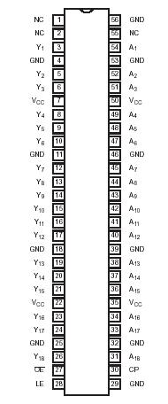
The 74ALVC162835A is an 18-bit universal bus driver. Data flow is controlled by output enable (OE), latch enable (LE) and clock inputs (CP).
When LE is HIGH, the A to Y data flow is transparent. When LE is LOW and CP is held at LOW or HIGH, the data is latched; on the LOW to HIGH transient of CP the A-data is stored in the latch/flip-flop.
The 74ALVC162835A is designed with 30 _series resistors in both HIGH or LOW output stages.
When OE of the 74ALVC162835A is LOW the outputs are active. When OE is HIGH, the outputs go to the high impedance OFF-state. peration of the OE input does not affect the state of the latch/flip -flop.
To ensure the high-impedance state of the 74ALVC162835A during power up or power down, OE should be tied to VCC through a pullup resistor; the minimum value of the resistor is determined by the current-sinking capability of the driver.