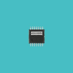
PinoutSpecificationsSupply voltage range, VCC . . . . . . . . . . . . . . . . . . . . . . . . . . . . . . . . . . . . . . . .. . . . . . . . . . . . . .0.5 V to 7 V Input voltage range, VI (see Note 1) . . . . . . . . . . . . . . . . . . . . . . . . . . . . . .. . . . . . . . .0.5 V to VCC + 0.5 V...
74ACT16241: PinoutSpecificationsSupply voltage range, VCC . . . . . . . . . . . . . . . . . . . . . . . . . . . . . . . . . . . . . . . .. . . . . . . . . . . . . .0.5 V to 7 V Input voltage range, VI (see Note...
SeekIC Buyer Protection PLUS - newly updated for 2013!
268 Transactions
All payment methods are secure and covered by SeekIC Buyer Protection PLUS.
Supply voltage range, VCC . . . . . . . . . . . . . . . . . . . . . . . . . . . . . . . . . . . . . . . .. . . . . . . . . . . . . .0.5 V to 7 V
Input voltage range, VI (see Note 1) . . . . . . . . . . . . . . . . . . . . . . . . . . . . . .. . . . . . . . . 0.5 V to VCC + 0.5 V
Output voltage range, VO (see Note 1) . . . . . . . . . . . . . . . . . . . . . . . . . . . . . . . . . . . . .0.5 V to VCC + 0.5 V
Input clamp current, IIK (VI < 0 or VI > VCC) . . . . . . . . . . . . . . . . . . . . . . . . . . . . . . . . . . . . . . . . . . . . .±20 mA
Output clamp current, IOK (VO < 0 or VO > VCC). . . . . . . . . . . . . . . . . . . . . . . . . . . . . . . . . . . . . . . . ±50 mA
Continuous output current, IO (VO = 0 to VCC). . . . . . . . . . . . . . . . . . . . . . . . . . . . . . . . . . . . . . . . . . ±50 mA
Continuous current through VCC or GND . . . . . . . . . . . . . . . . . . . . . . . . . . . . . . . . . . . . . . . . . . . . . . .±400 mA
Maximum package power dissipation at TA = 55°C (in still air) (see Note 2): DL package . . . . . . . . . . .1.2 W
Storage temperature range, Tstg . . . . . . . . . . . . . . . . . . . . . . . . . . . . . . . . . . . . . . . . . . . . . .65°C to 150°C
† Stresses beyond those listed under "absolute maximum ratings" may cause permanent damage to the device. These are stress ratings only, and functional operation of the device at these or any other conditions beyond those indicated under "recommended operating conditions" is not implied. Exposure to absolute-maximum-rated nditions for extended periods may affect device reliability.
NOTES: 1. The input and output voltage ratings may be exceeded if the input and output current ratings are bserved.
2. The maximum package power dissipation is calculated using a junction temperature of 150C and a board trace th of 750 mils.
The 74ACT16241 are 16-bit buffers or line drivers designed specifically to improve both the performance and density of 3-state memory address drivers, clock drivers, and bus-oriented receivers and transmitters. The devices can be used as four 4-bit buffers, two 8-bit buffers, or one 16-bit buffer. These devices provide true outputs and complementary output-enable (OE andOE) inputs.
The 74ACT16241 is packaged in TI's shrink small-outline package, which provides twice the I/O pin count and ionality of standard small-outline packages in the same printed-circuit-board area.
The 74ACT16241 is characterized for operation over the full military temperature range of 55°C to 125°C. The 241 is characterized for operation from 40°C to 85°C.