power supply circuit
Index 260
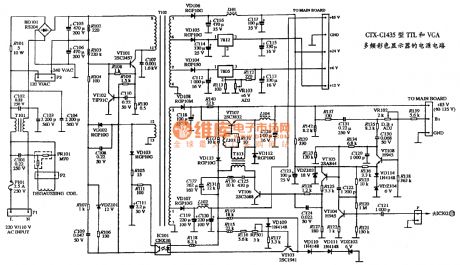
The power supply circuit diagram of CTX-C1435 type TTL and VGA multiple frequency color display
Published:2011/4/13 4:48:00 Author:may | Keyword: power supply, TTL, VGA, multiple frequency, color display
View full Circuit Diagram | Comments | Reading(1345)
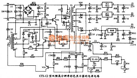
The power supply circuit diagram of CTX C2 type double frequency high resolution color display
Published:2011/4/13 4:45:00 Author:may | Keyword: power supply, double frequency, high resolution, color display
View full Circuit Diagram | Comments | Reading(524)
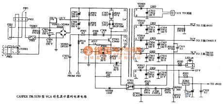
The power supply circuit diagram of CASPER TM-5159 type VGA color display
Published:2011/4/13 4:43:00 Author:may | Keyword: power supply, CASPER, VGA color display
View full Circuit Diagram | Comments | Reading(520)
The power supply circuit diagram of CASPER TM-5158 type VGA color display
Published:2011/4/13 4:41:00 Author:may | Keyword: power supply, CASPER, VGA color display
View full Circuit Diagram | Comments | Reading(517)
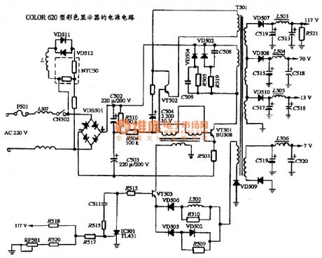
The power supply circuit diagram of COLOR 620 type color display
Published:2011/4/13 4:53:00 Author:may | Keyword: power supply, COLOR, color display
View full Circuit Diagram | Comments | Reading(587)
Automatic voltage regulator power supply circuit
Published:2011/4/13 4:21:00 Author:Ecco | Keyword: Automatic, voltage regulator, power supply
View full Circuit Diagram | Comments | Reading(5779)
The over-current protection transistor voltage regulating circuit
Published:2011/4/13 4:14:00 Author:Ecco | Keyword: over-current protection , transistor, voltage regulating
View full Circuit Diagram | Comments | Reading(537)
LTC4008 internal structure and external component connection diagram
Published:2011/4/12 3:29:00 Author:Nicole | Keyword: internal structure, external component
View full Circuit Diagram | Comments | Reading(547)
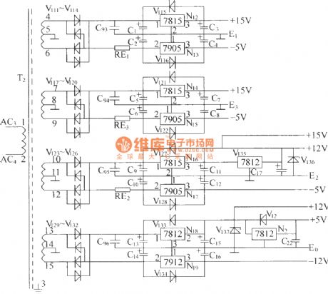
DZW75-48/50(50II) APS electrical schematic diagram
Published:2011/3/23 2:06:00 Author:muriel | Keyword: DZW75-48/50(50II), 7815, 7905, 7912, 7812, APS, electrical schematic diagram
View full Circuit Diagram | Comments | Reading(673)
TOP232Y 3 road output switching supply circuit diagram
Published:2011/3/24 3:24:00 Author:Ecco | Keyword: output switching supply
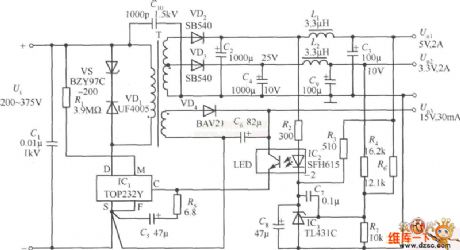
The TOP232 Y is used as four-terminal device. The efficiency of the power supply is 78%, the peak-crest value of output is 50 mv. Applied a single slab TOP232 Y, the total output of circuitry is 17.05 W. The d.c.inputs in the range of 200~375 V and 220 V/110 V. It needs to connect to rectifier filters, but no need to apply to input voltage doubler which make doubly rectification to 110 V voltage. The design develops soft start of TOP232 and undervoltage protection well, it has strict current limiting characteristic and high switch frequency characteristic, to make the magnetic core EE19 choosen by high - frequency transformer. Besides, TOP232 Y raises the spacing between the high pressure leak extreme and low-pressure port and lets up the electric leakage of pins, therefore power supply can used under worse environment. C1 is a type of d.c high frequency decoupling capacitance, and neglected when Ui is near from waiting source. The measuring resistance R1 could apply in settling the value of voltage UUV. When Rl=3.9MΩ, UUv=IUVRl=50μA×3.9MΩ=195V. When Ui<195 V, the supply will be cut off automaticly until Ui>195V. (View)
View full Circuit Diagram | Comments | Reading(1522)
CW494 Double-pointed convertor switching regulated power supply circuit diagram
Published:2011/3/27 20:30:00 Author:Ecco | Keyword: Double-pointed convertor , regulated power supply

The circuit diagram CW494 is a type of modulator integrated circuit made from of double-pointed convertor, including an error amplifier, reference voltage source, clock oscillator and vein breadth modulator,etc. The transformer T1 is a high - frequency transformer, which can deliver the energy to the burden. The T2 is a type of driving push transformer, which can deliver the two energizing pulses put by CW494 pulse modulator and amplifiered by energizing drive transistor. And the pulses reach the drive and base of switching tube in push-pull converter circuit diagram. After the variation of voltage and rectification of the pulses from samlping resistance by voltage transformer. The samlping resistance sends the pulses to the pulse modulator circuit diagram CW494, and to be the inverting input of error amplifier. Moreover, the switching power tube adopts rapid series F461. In the places of the feedback fo voltage , the input and output are connected directly. When the input, output need to be insulated, it can adopt photocoupler.
(View)
View full Circuit Diagram | Comments | Reading(906)
13.8V switching (voltage) regulator supply circuit diagram
Published:2011/3/20 22:47:00 Author:Ecco | Keyword: SI81206Z, 13.8V supply, switching (voltage) regulator
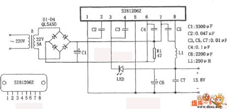
The 13.8 V switching (voltage) regulator supply is composed of SI81206 Z mold mass. The 13.8 V's power supply is used as a base station, car to carry an isoelectronic instrument. It has the features of high efficient, simple structure, steady performance.etc. (View)
View full Circuit Diagram | Comments | Reading(1826)
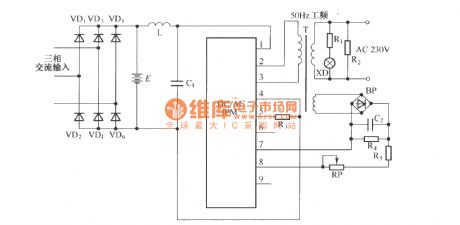
50Hz/1000W Inverterd power supply diagram with DC/AC IPM module
Published:2011/3/23 21:22:00 Author:muriel | Keyword: 50Hz/1000W, Inverterd power supply diagram , DC/AC IPM module
View full Circuit Diagram | Comments | Reading(1623)
Active clamped RDCLI power circuit
Published:2011/3/23 21:56:00 Author:muriel | Keyword: Active , clamped, RDCLI , power circuit
View full Circuit Diagram | Comments | Reading(555)
Self-control digital inverter power supply circuit diagram:1.2V rising to 9V
Published:2011/4/13 2:05:00 Author:Ecco | Keyword: Self-control, digital inverter, power supply

It does not require the establishment of a separate power switch or transformation to switches in the table. The circuit has the advantages of low power consumption, stability and reliability, no effect on instrument accuracy and so on. The transformer T in the circuit is E3-type core, to cut off each corner and process to be the mouth shape, L2 is inside while LJ is outside. When the inverter power supply works, the battery current is about 70mA. As shown in the chart:
(View)
View full Circuit Diagram | Comments | Reading(2508)
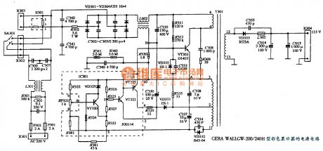
The power supply circuit diagram of GERAT WALL GW-200/200H type color display
Published:2011/4/12 4:32:00 Author:may | Keyword: power supply, GERAT WALL, color display
View full Circuit Diagram | Comments | Reading(664)
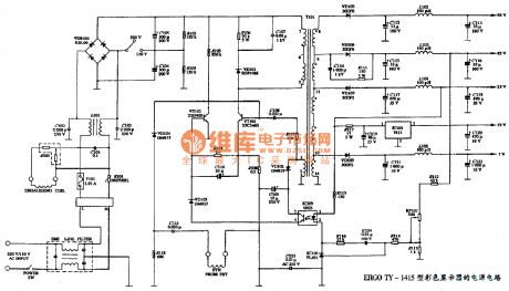
The power supply circuit diagram of ERGO TY-1415 type color display
Published:2011/4/12 4:31:00 Author:may | Keyword: power supply, ERGO, color display
View full Circuit Diagram | Comments | Reading(515)
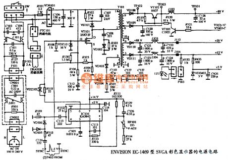
The power supply circuit diagram of ENVISION EC-1469 type SVGA color display
Published:2011/4/12 4:27:00 Author:may | Keyword: power supply, ENVISION, SVGA color display
View full Circuit Diagram | Comments | Reading(1108)
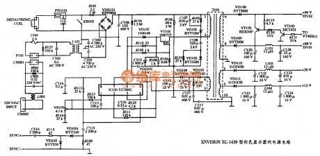
The power supply circuit diagram of ENVISION EC-1439 type color dispaly
Published:2011/4/12 4:21:00 Author:may | Keyword: power supply, ENVISION, color dispaly
View full Circuit Diagram | Comments | Reading(639)
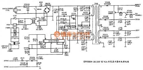
The power supply circuit diagram of ENVISION CM-335F type VGA color dispaly
Published:2011/4/12 4:15:00 Author:may | Keyword: power supply, ENVISION, VGA color dispaly
View full Circuit Diagram | Comments | Reading(523)
| Pages:260/291 At 20241242243244245246247248249250251252253254255256257258259260Under 20 |
Circuit Categories
power supply circuit
Amplifier Circuit
Basic Circuit
LED and Light Circuit
Sensor Circuit
Signal Processing
Electrical Equipment Circuit
Control Circuit
Remote Control Circuit
A/D-D/A Converter Circuit
Audio Circuit
Measuring and Test Circuit
Communication Circuit
Computer-Related Circuit
555 Circuit
Automotive Circuit
Repairing Circuit
