Measuring and Test Circuit
Index 9
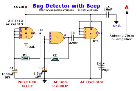
Bug Detector with Beep
Published:2013/2/17 20:21:00 Author:muriel | Keyword: Bug Detector, Beep
View full Circuit Diagram | Comments | Reading(1154)
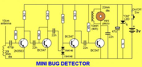
Mini Bug Detector
Published:2013/2/17 20:21:00 Author:muriel | Keyword: Mini Bug Detector
View full Circuit Diagram | Comments | Reading(1488)
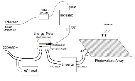
Solar Energy Meter
Published:2013/1/31 19:52:00 Author:muriel | Keyword: Solar Energy Meter
View full Circuit Diagram | Comments | Reading(1950)
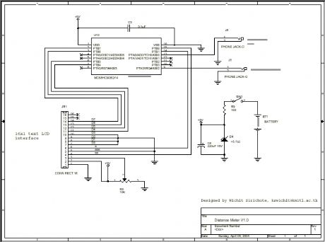
Electronic Distance Meter
Published:2013/1/30 21:01:00 Author:muriel | Keyword: Electronic Distance Meter
View full Circuit Diagram | Comments | Reading(1736)
Unijunction transistor trigger capacity detection circuit
Published:2013/1/30 1:25:00 Author:Ecco | Keyword: Unijunction transistor , trigger capacity, detection
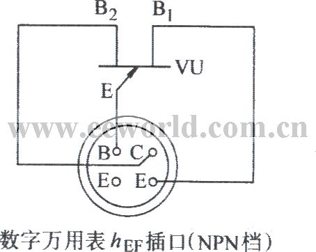
DMM hEF spigot (NPN block)
(View)
View full Circuit Diagram | Comments | Reading(939)
PIC Harmonic Distortion Meter
Published:2013/1/29 21:27:00 Author:muriel | Keyword: PIC , Harmonic, Distortion Meter
View full Circuit Diagram | Comments | Reading(1190)
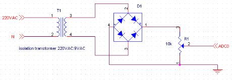
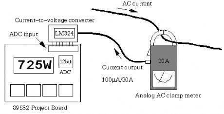
Simple Power Meter
Published:2013/1/29 1:34:00 Author:muriel | Keyword: Simple , Power Meter
View full Circuit Diagram | Comments | Reading(1399)
Digital electronic watch calibrator (CD4518, CD4011)
Published:2013/1/25 1:44:00 Author:Ecco | Keyword: Digital , electronic watch calibrator
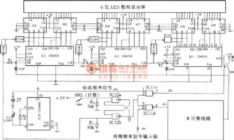
Quartz digital electronic watches have high timing accuracy, and accuracy calibration is required in the production or after repairing. The dedicated calibration instrument is expensive, and it is not suitable for amateur. You can use a homemade single CMOS digital circuit, it is cheap and applicable The following homemade digital electronic table calibrator is shown as figure. IC4 ~ IC9 use seven-segment decoder driver circuit CD4543; IC10, IC11 use CD4011, IC12 selects four - two -input NOR gate CD4001.
(View)
View full Circuit Diagram | Comments | Reading(3364)
Sixteen-channel digital display automatic inspection circuit (CD4520, CD4511, CD4067)
Published:2013/1/25 1:18:00 Author:Ecco | Keyword: Sixteen-channel , digital display, automatic inspection
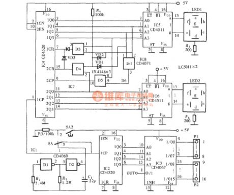
Automatic inspection circuit is used for the detection and control of multiple production equipment, the inspection circuit can make timing inspection for 16 sets of production equipments. It consists of patrol pulse generator, sixteen automatic patrol circuit and channel digital circuit, and it is shown in the figure.
(View)
View full Circuit Diagram | Comments | Reading(2115)
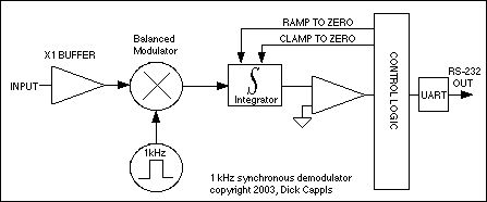
Experimental 1 KHz Synchronous Detector
Published:2013/1/25 1:22:00 Author:muriel | Keyword: Experimental , 1 KHz, Synchronous Detector
View full Circuit Diagram | Comments | Reading(1021)
Rapid heart rate meter (CD4518, CD4046, CD4511)
Published:2013/1/24 1:38:00 Author:Ecco | Keyword: Rapid , heart rate , meter
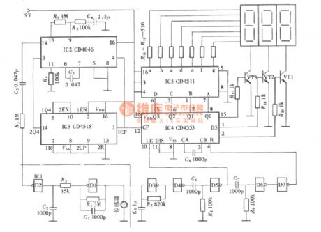
Heart rate meter and frequency meter are actually belong to the same class of measuring instruments, but heart rate meter's time the gate is just 1min rather than 1s. For A measuring instrument, 1 min measuring time is not only a long time, but it is difficult to ensure the accuracy of measurement. Therefore it must transform the measurement to match the rapid and accurate requirements. The figure shows a heart rate measuring instrument circuit, and it is consistent with the rapid and accurate requirements.
(View)
View full Circuit Diagram | Comments | Reading(3081)
The infrared pulse meter (NE555, CD4553, CD4543)
Published:2013/1/24 1:22:00 Author:Ecco | Keyword: infrared pulse meter

The so - called infrared pulse meter's sensor for picking up the signal uses infrared sensors. The circuit is shown as figure.
Figure (a) is the placement of the sensor and finger; (b) is schematic diagram; (c) is the Pin Function FIG of LM11, CD4049.
(View)
View full Circuit Diagram | Comments | Reading(2392)
The ceramic crystal Tester (CD4553, CD4040, CD4543)
Published:2013/1/24 1:18:00 Author:Ecco | Keyword: ceramic crystal Tester
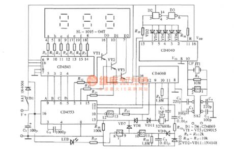
Ceramic crystal is the crystal oscillating element for infrared remote control transmitter, it has higher damage rate, and it is often difficult to determine whether it is good or bad in the overhaul. The detector shown in figure can quickly determine whether it is good or bad, so it provides a great convenience for overhaul. The instrument is actually a three-digit explicit frequency meter, and its reading unit is represented in kHz.
(View)
View full Circuit Diagram | Comments | Reading(5198)
Transistors simple test circuit diagram
Published:2013/1/23 1:11:00 Author:Ecco | Keyword: Transistors, simple test
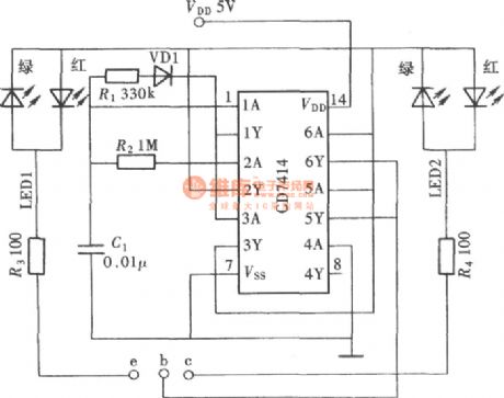
The transistor is one of the most commonly used devices in electronic circuits, and it is often to be tested, sometimes it is very troublesome to use a multimeter to test. The instrument is simple to manufacture, and the test results are very good, and it can fully meet the general requirements. The circuit schematic is shown as figure.
(View)
View full Circuit Diagram | Comments | Reading(1577)
DC capacitor tester with 555
Published:2013/1/23 2:36:00 Author:Ecco | Keyword: DC capacitor tester, 555
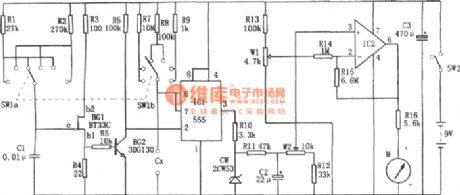
The tester is composed of the pulse generator, monostable trigger, DC amplifier and header indicating circuit. It can measure npF to 10μF capacitance. The range is divided into 0 ~ 100PF, 0 ~ 1nF, 0 ~ 10nF, 0 ~ 100nF, 0 ~ 1μF, 0 ~ 10μF.
(View)
View full Circuit Diagram | Comments | Reading(1657)
RF Transmission and detection/measurement example
Published:2013/1/22 21:20:00 Author:muriel | Keyword: RF Transmission , detection, measurement
View full Circuit Diagram | Comments | Reading(810)
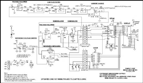
1 KHZ INDUCTANCE METER PROJECT
Published:2013/1/22 21:09:00 Author:muriel | Keyword: 1 KHZ, INDUCTANCE METER, PROJECT
View full Circuit Diagram | Comments | Reading(3754)
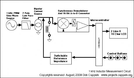
Experimental 1 Khz Inductance Meter
Published:2013/1/22 21:09:00 Author:muriel | Keyword: Experimental, 1 Khz, Inductance Meter
View full Circuit Diagram | Comments | Reading(1309)
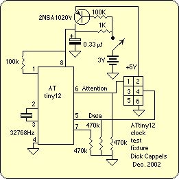
Timekeeping test circuit
Published:2013/1/22 20:58:00 Author:muriel | Keyword: Timekeeping test circuit
View full Circuit Diagram | Comments | Reading(782)
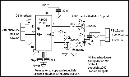
DS interface test tool
Published:2013/1/22 20:56:00 Author:muriel | Keyword: DS interface , test tool
View full Circuit Diagram | Comments | Reading(858)
| Pages:9/101 1234567891011121314151617181920Under 20 |
Circuit Categories
power supply circuit
Amplifier Circuit
Basic Circuit
LED and Light Circuit
Sensor Circuit
Signal Processing
Electrical Equipment Circuit
Control Circuit
Remote Control Circuit
A/D-D/A Converter Circuit
Audio Circuit
Measuring and Test Circuit
Communication Circuit
Computer-Related Circuit
555 Circuit
Automotive Circuit
Repairing Circuit
