
Circuit Diagram
Index 294
50 Ohm Long Line Driver
Published:2012/10/24 1:19:00 Author:muriel | Keyword: 50 Ohm , Long Line Driver

View full Circuit Diagram | Comments | Reading(1054)
4-Way Active Guitar Splitter
Published:2012/10/24 1:17:00 Author:muriel | Keyword: 4-Way , Active , Guitar Splitter

View full Circuit Diagram | Comments | Reading(4105)
2-Way Passive Guitar Splitter
Published:2012/10/24 1:16:00 Author:muriel | Keyword: 2-Way , Passive, Guitar Splitter

View full Circuit Diagram | Comments | Reading(4358)
150 Ohm Line to 600 Ohm Load Application
Published:2012/10/24 1:16:00 Author:muriel | Keyword: 150 Ohm , Line to 600 Ohm , Load Application

View full Circuit Diagram | Comments | Reading(1079)
Batteries charger & PSU - ideal for digital cameras
Published:2012/10/24 1:13:00 Author:muriel | Keyword: Batteries charger, PSU

This circuit was created for digital cameras. It's known the digital cameras have considerable power consumption. For example my camera Minolta E223 requires approximately 800 mA. In practice a mains power supply or high capacity NiMH accumulators (batteries) can satisfy this demand.
This circuit consists of two parts, charger and adapter. The transformer, rectifier bridge and buffer condensator are common. Adapter is quite simply its main part is an adjustable voltage regulator LM 317 according to usual setting. Output is a suitable for camera jack plug. Voltage can be adjusted in range 2-9 V.In the charger circuit a 7805 fixed voltage regulator works as current generator assured constant current during charging. This charging current can be adjusted with the 100 /1W potentiometer in range about 50-300 mA indicated by a small current measuring instrument. From one to four batteries can be charged simultaneously. The switch must be set according to number of batteries, and charging current of batteries given by manufacturer must be adjusted. This circuit doesn't measure charging time and charging condition of batteries. Manufacturers give charging time, usually 14-16 h. I solved this problem with a simply, cheap mechanical mains timer. I think its accuracy is sufficient. (View)
View full Circuit Diagram | Comments | Reading(1149)
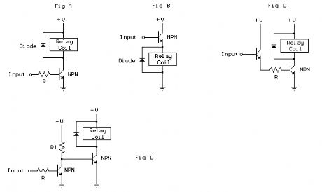
Controlling a relay with a digital logic level.
Published:2012/10/24 1:09:00 Author:muriel | Keyword: relay, digital logic level
View full Circuit Diagram | Comments | Reading(743)
4 Decoded Toggle Switches
Published:2012/10/24 1:08:00 Author:muriel | Keyword: 4 Decoded , Toggle Switches

The circuit above illustrates using the IR receiver module along with a PIC12F629 microcontroller to decode 5 individual IR remote control keys so the circuit will only toggle one of the 4 outputs when a particular key is pressed. The 5th key is assigned to the master clear function that toggles off the 4 outputs. Works with most hand held IR remote controls that send a single data stream. However, some remotes send multiple groups of data and only the first set of 40 bits or less will be recognized. This may result in the circuit responding to more than one key, or a single key may control more than one toggle switch. In most cases this problem can be resolved by selecting an alternate function on the remote such as (TV, DVD, SAT, AUX, Etc.). Circuit power supply is not critical and should operate on any voltage from 2 to 5 volts DC. I use a single 3.6 volt recharageable lithium battery such as found in cell phones. (View)
View full Circuit Diagram | Comments | Reading(939)
IR Receiver Toggle Switch
Published:2012/10/24 1:07:00 Author:muriel | Keyword: IR Receiver, Toggle Switch

View full Circuit Diagram | Comments | Reading(789)
Ignition Coil Buzz Box
Published:2012/10/24 1:06:00 Author:muriel | Keyword: Ignition Coil , Buzz Box
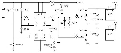
Here's a circuit to create a buzzcoil using a standard automotive ignition coil. A 556 dual timer is used to establish the frequency and duty cycle of the coil current. One of the timers is used as an oscillator to generate the 200 Hz rectangular waveform needed to control the (IRF740 MOSFET) while the second timer switches the oscillator on and off as the breaker points open and close (closed = on). The result is a steady stream of sparks from the ignition coil spaced about 5 milliseconds apart while the breaker points are closed.
Operation:
Pin 8 and 12 are the threshold and trigger inputs of one timer which are driven by the breaker points and produce an inverted signal at the timer output (pin 9). When the points are closed to ground, pin 9 will be high and visa versa. The signal at pin 9 controls the reset line (pin 4) of the second timer and holds the output at pin 5 low while pin 4 is low and pins 8 and 12 are high (points open). The 15K and 4.7K resistors and 0.33uF capacitor are the timing components that establish the frequecy and duty cycle of the second timer which is about 4 milliseconds for the positive interval and 2 milliseconds for the negative. During the positive time interval, the MOSFET gates are held high which causes the ignition coil current to rise to about 4 amps. This equates to about 80 millijoules of energy in the coil which is released into the spark plug when the timer output (pin 5) moves to ground, turning off the MOSFET. A 12 volt zener diode is placed at the junction of the 10 and 27 ohm resistors to insure the MOSFET gate input never goes above 12 volts or lower than -0.7 volts. A 200 volt/5 watt zener is used at the MOSFET drain to limit the voltage to +200 and lengthen the spark duration. The circuit should operate reliably with a shorted plug, however operating the circuit with no load connected (plug wires fallen off, etc.) may cause a failure due to most of the power being absorbed by the zener. You can also use a transient voltage suppressor (TVS) such as the 1.5KE200A or 1.5KE300A in place of the zener. It's probably a better part, but hard to obtain. (View)
View full Circuit Diagram | Comments | Reading(1115)
Pinewood Derby Finish Line Lamps
Published:2012/10/24 0:56:00 Author:muriel | Keyword: Pinewood Derby, Finish Line, Lamps

The finish line circuit below detects the first of three cars to cross the line and illuminates a 25 watt 120 VAC lamp indicating the winning lane. Three photo transistors are used which can be embedded into the track with a light shining down onto the finish line so that as the car crosses over the sensor, the light is blocked, activating the relay and lighting the lamp for the appropriate track. The light source should be an incandescent type, florescent lights may not work due to low infra-red content. The circuit was tested using a 100 watt incandescent light fixture about 3 feet above the photo transistors.
The photo transistors are connected so that a logic low (0 volts) normally appears at the input to a NAND gate and as a car crosses the line blocking light to the transistor the logic level will move high (+6 volts). The resulting logic low level from the output of the gate (3 input NAND) is fed to a SET/RESET latch made from two dual input NAND gates (1/2 of a 74HC00) the (logic high) output of which controls the MPS2222A buffer transistor and solid state relay. The inverted output of the latch (logic low) is connected back to the remaining two (3 input NAND gate) inputs locking them out. Two extra 74HC00 gates are not used and should have their inputs (pins 9,10,12,13) connected to ground to avoid possible oscillation. The circuit is reset with a momentary push button connected to the reset side of each latch. The reset button may need to be pressed after power is first applied. Components for the circuit may be obtained from Radio Shack, however the RSU numbers may need to be special ordered or obtained from another source. The 74HC00 and 74HC10 are CMOS parts and should be handled carefully to avoid possible damage from static electricity. You may want to use IC sockets so the wiring can be completed before the ICs are inserted into the sockets. You can briefly touch a grounded surface (computer chassis or other metal ground surface) just before handling CMOS circuits to reduce the possibility of damage from static electricity. (View)
View full Circuit Diagram | Comments | Reading(1053)
Game Show Indicator Lights (Who's First)
Published:2012/10/24 0:55:00 Author:muriel | Keyword: Game Show, Indicator Lights
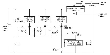
The circuit below turns on a light corresponding to the first of several buttons pressed in a Who's First game. Three stages are shown but the circuit can be extended to include any number of buttons and lamps.
Three SCRs (silicon controlled rectifiers) are connected with a common cathode resistor (50 ohm) so that when any SCR conducts, the voltage on the cathodes will rise about 7 volts above the voltage at the junction of the 51K and 1K ohm resistors and prevent triggering of a second SCR. When all lamps are off, and a button is pressed, the corresponding SCR is triggered due to the voltage at the divider junction being higher than the cathode. Once triggered, the SCR will remain conducting until current is interrupted by the reset switch. Or, you can just turn the power off and back on.
A 50 ohm, 5 watt resistor was selected to produce a 10 volt drop at 200 mA when a single 25 watt lamp comes on. Higher wattage lamps would require a lower value resistor, and visa versa. For example to use 60 watt lamps and maintain the 10 volt drop, the peak current would be 60/160 = 375 mA and the resistance would be E/I = 10/.375 or about 27 ohms at 3.75 watts. The SCRs are Sensitive Gate' types which trigger on about 200 uA and the gate current is around 1.5 mA when the first button is pressed. The 1N914 diodes in series with the buttons gates are used to prevent a reverse voltage on the gate when a button is pressed after an SCR is conducting. The two 51 ohm resistors will be fairly large in physical size (compared to a 1/4 watt size) and should be rated for 5 watts of power or more. Use caution and do not touch any components while the circuit is connected to the AC line. (View)
View full Circuit Diagram | Comments | Reading(1398)
120VAC Lamp Chaser
Published:2012/10/24 0:54:00 Author:muriel | Keyword: 120VAC , Lamp Chaser
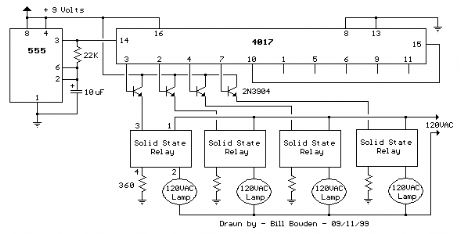
This circuit is basically the same as the 10 channel LED sequencer with the addition of solid state relays to control the AC lamps. The relay shown in the diagram is a Radio Shack 3 amp unit (part no. 275-310) that requires 1.2 volts DC to activate. No current spec was given but I assume it needs just a few milliamps to light the internal LED. A 360 ohm resistor is shown which would limit the current to 17 mA using a 9 volt supply. I tested the circuit using a solid state relay (of unknown type) which required only 1.5 mA at 3 volts but operates up to 30 volts DC and a much higher current. The chaser circuit can be expanded up to 10 channels with additional relays and driver transistors. The 4017 decade counter reset line (pin 15) is connected to the fifth count (pin 10) so that the lamps sequence from 1 to 4 and then repeat. For additional stages the reset pin would be connected to a higher count. (View)
View full Circuit Diagram | Comments | Reading(1291)
Constant Current Battery Charger
Published:2012/10/24 0:54:00 Author:muriel | Keyword: Constant Current, Battery Charger

A simple method of charging a battery from a higher voltage battery is shown in the circuit below to the left. Only one resistor is needed to set the desired charging current and is calculated by dividing the difference in battery voltages by the charge current. So, for example if 4 high capacity (4000 mA hour) ni-cads are to be charged at 300 mA from a 12 volt battery, the resistor needed would be 12-(4*1.25)/0.3 = 23.3 ohms, or 22 ohms which is the nearest standard value. The power rating for the resistor is figured from the square of the current times the resistance or (0.3)^2 * 22 = 2 watts which is a standard value but close to the limit, so a 5 watt or greater value is recommended.
The circuit below (right) illustrates a constant current source used to charge a group of 1 to 10 ni-cad batteries. A 5K pot and 3.3K resistor are used to set the voltage at the emitter of the TIP 32 which establishes the current through the output and 10 ohm resistor. The emitter voltage will be about 1.5 volts above the voltage at the wiper of the pot, or about 1/2 the supply voltage when the wiper is in the downward most position. In the fully upward position the transistors will be turned off and the current will be close to zero. This yields a current range of 0 to (0.5*input)/10 or 0 to 850 milliamps using a 17 volt input. This produces about 7 watts of heat dissipation at maximum current for the 10 ohm resistor, so a 10 watt or greater rating is needed. The TIP 32 transistor will also dissipate about 7 watts if the output is shorted and needs to be mounted on a heat sink. If more than 4 cells are connected, the maximum current available will decrease and limits the current setting to about 100 milliamps for 10 cells. The usual charge rate for high capacity (4AH) 'D' cells is 300 to 400 milliamps for 14 hours and 100 milliamps for (1.2AH) 'C' or 'D' cells. For small 9 volt batteries the charge rate is 7 milliamps for 14 hours which would be difficult to set and probably unstable, so you could reduce the range to 0-20 mA by using a 750 ohm resistor in place of the 10. The charge current can be set by connecting a milliamp meter across the output (with the batteries disconnected) and then adjusting the control to the desired current, or by monitoring the voltage across the 10 ohm resistor (1 volt = 100 mA) or (1 volt = 1.33 mA using a 750 ohm resistor). The current control should be set to minimum (wiper in uppermost position) before power is applied, and then adjusted to the desired current.
The circuit (lower right) illustrates using a LM317 variable voltage regulator as a constant current source. The voltage between the adjustment terminal and the output terminal is always 1.25 volts, so by connecting the adjustment terminal to the load and placing a resistor (R) between the load and the output terminal, a constant current of 1.25/R is established. Thus we need a 12 ohm resistor (R) to get 100mA of charge current and a 1.2 ohm, 2 watt resistor for 1 amp of current. A diode is used in series with the input to prevent the batteries from applying a reverse voltage to the regulator if the power is turned off while the batteries are still connected. It's probably a good idea to remove the batteries before turning off the power. (View)
View full Circuit Diagram | Comments | Reading(0)
12 Stage Neon Sequencer (NE-2 / NE-51)
Published:2012/10/24 0:53:00 Author:muriel | Keyword: 12 Stage, Neon Sequencer, NE-2 , NE-51

This circuit is similar to the LED clock using 12 neon indicator lamps instead of LEDs. It operates from 2 high capacity ni-cad cells (2.5 volts) which keep it going for a couple weeks. High voltage (70 volts) for the neon lamps is obtained from a small switching power supply using a 74HC14 Schmitt trigger squarewave oscillator, high voltage switching transistor, and 10 mH high Q inductor. Most any small PNP transistors can be used that have a C/E voltage rating of 80 or more. The inverter stage (pins 5,6) is not needed and is just an extra stage. An adjustable low frequency oscillator made from two of the inverter stages generates the clock signal for the 74HCT393 binary counter. In this circuit, the timing capacitor should be non-polarized since the capacitor will charge in both directions, so two 6.8 uF tantalum caps were used back to back which yields about 3.3 uF. The 75K resistor in series with pin 1 limits the current through the input protection diodes when the capacitor voltage exceeds the supply voltage. This resistor may not be necessary with small capacitors at low voltage but was added as a precaution. The binary counts are decoded into 1 of 12 outputs by the 74HCT138 decoders and operates the same way as in the 28 LED clock circuit. The sequence can be extended to 16 by omitting the reset circuit and tying pins 2 and 13 of the counter to ground. (View)
View full Circuit Diagram | Comments | Reading(673)
Flashing Neons (NE-2 / NE-51)
Published:2012/10/24 0:52:00 Author:muriel | Keyword: Flashing Neons , NE-2 , NE-51

In this circuit, one, two or three neon indicator bulbs can be made to flash in sequence at rates determined by the R and C values. In the single stage circuit, using one lamp, the capacitor charges through the resistor until the ionization potential of the neon is reached (about 70 volts) and then discharges quickly through the lamp until the voltage falls below what is needed to sustain the lamp which is approximately 45 volts. The cycle then repeats at a rate of about 3 Hz for values shown. Smaller R or C values increase frequency, larger values decrease frequency. All capacitors should be the non-polarized variety with a 100 volt or more rating. For more than 3 stages, the lamps may need to be matched for similar turn-on voltages. (View)
View full Circuit Diagram | Comments | Reading(969)
Light Activated Relay
Published:2012/10/24 0:51:00 Author:muriel | Keyword: Light Activated, Relay

This is same circuit as above with the addition of a photo resistor to trigger the flip flop instead of a push button. The bias resistor in series with photo resistor was chosen so that sufficient voltage is present at the base of the 2N3904 to supply current to the circuit in ambient lighting conditions. The circuit should toggle when the photo resistor is hit by a flashlight beam or other fast changing light source. Slow changes in light intensity will have no effect unless the light gets too bright to maintain sufficient bias for the 2N3904. (View)
View full Circuit Diagram | Comments | Reading(1380)
LM317T Voltage Regulator with Pass Transistor
Published:2012/10/23 22:00:00 Author:muriel | Keyword: LM317T , Voltage Regulator, Pass Transistor
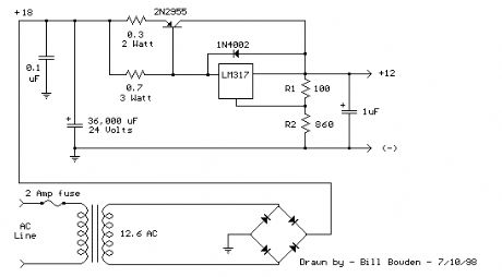
The LM317T output current can be increased by using an additional power transistor to share a portion of the total current. The amount of current sharing is established with a resistor placed in series with the 317 input and a resistor placed in series with the emitter of the pass transistor. In the figure below, the pass transistor will start conducting when the LM317 current reaches about 1 amp, due to the voltage drop across the 0.7 ohm resistor. Current limiting occurs at about 2 amps for the LM317 which will drop about 1.4 volts across the 0.7 ohm resistor and produce a 700 millivolt drop across the 0.3 ohm emitter resistor. Thus the total current is limited to about 2+ (.7/.3) = 4.3 amps. The input voltage will need to be about 5.5 volts greater than the output at full load and heat dissipation at full load would be about 23 watts, so a fairly large heat sink may be needed for both the regulator and pass transistor. The filter capacitor size can be approximated from C=IT/E where I is the current, T is the half cycle time (8.33 mS at 60 Hertz), and E is the fall in voltage that will occur during one half cycle. To keep the ripple voltage below 1 volt at 4.3 amps, a 36,000 uF or greater filter capacitor is needed. The power transformer should be large enough so that the peak input voltage to the regulator remains 5.5 volts above the output at full load, or 17.5 volts for a 12 volt output. This allows for a 3 volt drop across the regulator, plus a 1.5 volt drop across the series resistor (0.7 ohm), and 1 volt of ripple produced by the filter capacitor. A larger filter capacitor will reduce the input requirements, but not much. (View)
View full Circuit Diagram | Comments | Reading(934)
LM317T Variable Voltage Regulator
Published:2012/10/23 21:45:00 Author:muriel | Keyword: LM317T , Variable Voltage, Regulator
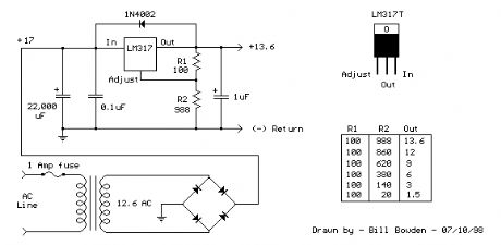
The LM317T is a adjustable 3 terminal positive voltage regulator capable of supplying in excess of 1.5 amps over an output range of 1.25 to 37 volts. The device also has built in current limiting and thermal shutdown which makes it essentially blow-out proof.
Output voltage is set by two resistors R1 and R2 connected as shown below. The voltage across R1 is a constant 1.25 volts and the adjustment terminal current is less than 100uA. The output voltage can be closely approximated from Vout=1.25 * (1+(R2/R1)) which ignores the adjustment terminal current ``but will be close if the current through R1 and R2 is many times greater. A minimum load of about 10mA is required, so the value for R1 can be selected to drop 1.25 volts at 10mA or 120 ohms. Something less than 120 ohms can be used to insure the minimum current is greater than 10mA. The example below shows a LM317 used as 13.6 volt regulator. The 988 ohm resistor for R2 can be obtained with a standard 910 and 75 ohm in series.
When power is shut off to the regulator the output voltage should fall faster than the input. In case it doesn't, a diode can be connected across the input/output terminals to protect the regulator from possible reverse voltages. A 1uF tantalum or 25uF electrolytic capacitor across the output improves transient response and a small 0.1uF tantalum capacitor is recommended across the input if the regulator is located an appreciable distance from the power supply filter. The power transformer should be large enough so that the regulator input voltage remains 3 volts above the output at full load, or 16.6 volts for a 13.6 volt output. (View)
View full Circuit Diagram | Comments | Reading(1103)
Solar Cell Boost Converter
Published:2012/10/23 20:29:00 Author:muriel | Keyword: Solar Cell, Boost Converter

The boost converter is used to charge batteries from low voltage solar arrays. Results were obtained using 3X3 cells that deliver about 400 millivolts at 1 amp. The pictured panel array contains 20 cells in series and generates about 8 watts at 8 volts in bright sunlight and was assembled on a 12 X 16 picture frame. Efficiency of the converter measured 87% and delivers almost 600 milliamps into a 12 volt SLA battery. Efficiency drops to about 72% using 4 single cells in series (pictured above) charging the same 12 volt battery at around 70mA. The current was a little low due to a couple broken corners. A third test was made using a single cell at 0.4 volt charging a 6 volt battery, but efficiency was only about 55%. The cells were purchased from solarcells101.com in slightly damaged condition with chipped edges and a few tiny cracks, but still perform well and sell at discount. There are also many good deals on ebay. (View)
View full Circuit Diagram | Comments | Reading(1562)
RC Notch Filter (Twin T)
Published:2012/10/23 20:23:00 Author:muriel | Keyword: RC Notch Filter , Twin T

The twin T notch filter can be used block an unwanted frequency or if placed around an op-amp as a bandpass filter. The notch frequency occurs where the capacitive reactance equals the resistance (Xc=R) and if the values are close, the attenuation can be very high and the notch frequency virtually eliminated. The insertion loss of the filter will depend on the load that is connected to the output, so the resistors should be of much lower value than the load for minimal loss. At audio frequencies, the filter could function as a bass and treble boost circuit by attenuating the mid range frequencies. Using 1.5K resistors and 0.1uF capacitors, the band stop at -10dB is about 500 Hz to 2Khz. The depth and width of the response can be adjusted somewhat with the 0.5R value and by adding some resistance across the C values. If the circuit is used around an op-amp as a bandpass filter, the response may need to be dampened to avoid oscillation. (View)
View full Circuit Diagram | Comments | Reading(1164)
| Pages:294/2234 At 20281282283284285286287288289290291292293294295296297298299300Under 20 |
Circuit Categories
power supply circuit
Amplifier Circuit
Basic Circuit
LED and Light Circuit
Sensor Circuit
Signal Processing
Electrical Equipment Circuit
Control Circuit
Remote Control Circuit
A/D-D/A Converter Circuit
Audio Circuit
Measuring and Test Circuit
Communication Circuit
Computer-Related Circuit
555 Circuit
Automotive Circuit
Repairing Circuit