Signal Processing
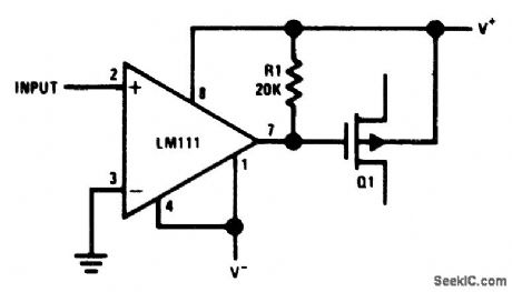
Zero_crossing_detector_for_MOS
Published:2009/7/24 4:21:00 Author:Jessie | From:SeekIC

Fig. 15-7 In this zero-crossing detector, the ground terminal of the LM111 is connected to V-. With±15-V supplies, the signal swing delivered to the gate of Q1 is also ±15 V, so the circuit is well suited for MOS (particularly where the gain or feedback of a circuit must be changed at some precisely determined signal level). The circuit can be modified to work with JFETs. National semiconductor Linear Applications Handbook 1991, p 1204.
Reprinted Url Of This Article:
http://www.seekic.com/circuit_diagram/Signal_Processing/Zero_crossing_detector_for_MOS.html
Print this Page | Comments | Reading(3)

Article Categories
power supply circuit
Amplifier Circuit
Basic Circuit
LED and Light Circuit
Sensor Circuit
Signal Processing
Electrical Equipment Circuit
Control Circuit
Remote Control Circuit
A/D-D/A Converter Circuit
Audio Circuit
Measuring and Test Circuit
Communication Circuit
Computer-Related Circuit
555 Circuit
Automotive Circuit
Repairing Circuit
Code: