Signal Processing
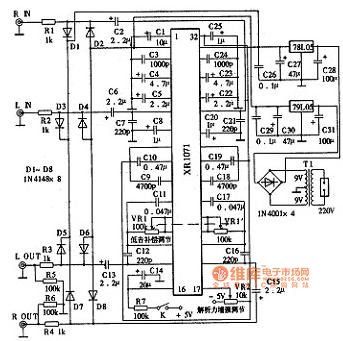
XR1071 application circuit diagram
Published:2014/1/5 20:27:00 Author: | Keyword: XR1071 application circuit diagram, XR1071 | From:SeekIC


The practical application of the circuit XR1071 chip. Its performance is relatively good, signal-to-noise ratio as high as 95 db, total harmonic distortion, compensation adjustment range is bigger also, working voltage of + 5 v power supply, power consumption is only + 15 ma. VR2 for resolving power enhanced potentiometer, can make the own empowerment circuit after processing the audio signal analysis of the force, clarity from 0 dB to 9.7 dB. VR1 for low frequency component ascending potentiometer, adjusting range of 0 ~ 9.9 dB, improve low frequency in order to keep a good balance of high, medium and low frequency components. Adjust both to cooperate with each other, when the sound school to the state with the most natural and clear.
XR1071 application circuit diagram as shown
Reprinted Url Of This Article:
http://www.seekic.com/circuit_diagram/Signal_Processing/XR1071_application_circuit_diagram.html
Print this Page | Comments | Reading(3)

Article Categories
power supply circuit
Amplifier Circuit
Basic Circuit
LED and Light Circuit
Sensor Circuit
Signal Processing
Electrical Equipment Circuit
Control Circuit
Remote Control Circuit
A/D-D/A Converter Circuit
Audio Circuit
Measuring and Test Circuit
Communication Circuit
Computer-Related Circuit
555 Circuit
Automotive Circuit
Repairing Circuit
Code: