Signal Processing
Ward Caller Six
Published:2011/7/17 0:53:00 Author:Felicity | Keyword: Ward Caller | From:SeekIC

Work of the circuit
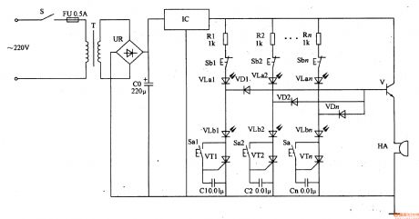
The circuit consists of power circuit, call control circuit and light and sound call circuit. (It is showed in picture 9-89.)
Power circuit consists of Power switch S, fuse FU, power transformer T, bridge rectifier, UR, filter capacitor CO and three-terminal regulator IC IC.
Call control circuit consists of control buttons Sa1-San, capacitors Cl-Cn, thyristor VTl-VT2 and light-emitting diode VLal, VLan.
Light and sound call circuit consists of resistors Rl-Rn, reset button Sbl-Sbn, LED VLbl-VLbn, diode VDl-VDn, transistor V and buzzer HA.
When Sal-San are not pressed, VT1-VTn and V are all cut off and VLa1-VLan and VLa1-VLbn are off, and HA is noiseless.
When one of Sa1-San is pressed, the thyristor connect to it is triggered on and the LED in this branch is on to indicate the patient bed number. At the same time V is
saturated and on. HA beeps. While the medical personnel receives the ward calling signal , they press the reset button, and the thyristor and the transistor cut off, and the
two LEDs are off, then HA stop beeping.
Reprinted Url Of This Article:
http://www.seekic.com/circuit_diagram/Signal_Processing/Ward_Caller_Six.html
Print this Page | Comments | Reading(3)

Article Categories
power supply circuit
Amplifier Circuit
Basic Circuit
LED and Light Circuit
Sensor Circuit
Signal Processing
Electrical Equipment Circuit
Control Circuit
Remote Control Circuit
A/D-D/A Converter Circuit
Audio Circuit
Measuring and Test Circuit
Communication Circuit
Computer-Related Circuit
555 Circuit
Automotive Circuit
Repairing Circuit
Code: