Signal Processing
Ward Caller Eight
Published:2011/7/17 0:46:00 Author:Felicity | Keyword: Ward Caller | From:SeekIC

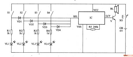
This ward caller is consists of calling-control circuit and music circuit.
Aalling-control circuit consists of callswitchesSl-S4,resistorsR1-R4,light-emitting diodesVLl-VL4anddiodeVDl-VD4.
Music circuit consists of resistorR5,transistorV,musicintegrated circuitIC andspeaker BL .
When one of the call switches S1-S4 is pressed, the IC is triggered on to work, the music electrical signal output by O/P is amplified by V to drive BL to send out music
sound; at the same time the LED in this branch is on to indicate the bed number of the patient. After the medical personnel receives the acousto-optic calling signal, they
reset S2 and press the reset button S0 to make IC reset and BL stops.
Only four calling circuitsare showed in the figure and the number of it can be adjusted according to actual need.
Reprinted Url Of This Article:
http://www.seekic.com/circuit_diagram/Signal_Processing/Ward_Caller_Eight.html
Print this Page | Comments | Reading(3)

Article Categories
power supply circuit
Amplifier Circuit
Basic Circuit
LED and Light Circuit
Sensor Circuit
Signal Processing
Electrical Equipment Circuit
Control Circuit
Remote Control Circuit
A/D-D/A Converter Circuit
Audio Circuit
Measuring and Test Circuit
Communication Circuit
Computer-Related Circuit
555 Circuit
Automotive Circuit
Repairing Circuit
Code: