Signal Processing
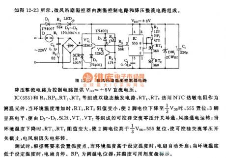
The temperature controller circuit of the 555 breeze ceiling fan
Published:2011/5/27 21:24:00 Author:Borg | Keyword: temperature controller, breeze ceiling fan | From:SeekIC

IC(555),R5,RP1,RT1,RT2 and so on form a dual steady state trigger circuit, RT1 and RT2 is fixed with NTC thermistor as the temperature detection device, when the environment temperature is rising, the resistances of RT1 and RT2 are getting down, and the 2-pin is in a 1/3 VDD LEV, 555 is offset, 3-pin is in a high LEV, then the controllable silicon AC zero-voltage switch which consists of D2~D5,SCR,VT1 and VT2 is conducting, the fan runs; when the environment temperature is getting down, the resistances of RT1 and RT2 is rising, and the LEV of 2-lead is higher than 1/3VDD, 555 is offset, then the controllable silicon AC zero-voltage switch is cut off and the fan stops due to lack of power.
Reprinted Url Of This Article:
http://www.seekic.com/circuit_diagram/Signal_Processing/The_temperature_controller_circuit_of_the_555_breeze_ceiling_fan.html
Print this Page | Comments | Reading(3)

Article Categories
power supply circuit
Amplifier Circuit
Basic Circuit
LED and Light Circuit
Sensor Circuit
Signal Processing
Electrical Equipment Circuit
Control Circuit
Remote Control Circuit
A/D-D/A Converter Circuit
Audio Circuit
Measuring and Test Circuit
Communication Circuit
Computer-Related Circuit
555 Circuit
Automotive Circuit
Repairing Circuit
Code: